
Ventilation Duct Sizing - Installation Designer's Guide
8 marca 2026 | Ventilation
Proper ventilation duct sizing is one of the key stages in designing a mechanical ventilation system. A duct that is too small means excessive noise and high flow resistance, while one that is too large unnecessarily increases costs and takes up valuable space. In this guide, we present a complete methodology for sizing round (spiro) and rectangular ducts, including formulas, tables and calculation examples.
If you need to quickly size a duct, use our ventilation duct sizing calculator, which automatically selects the diameter or duct dimensions based on the required airflow.
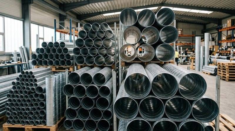
Fundamentals of Ventilation Duct Sizing
Ventilation duct sizing involves determining a cross-section that ensures the transport of the required amount of air at an acceptable flow velocity and pressure drop. In design practice, two methods are used:
- Constant velocity method - the duct is sized so that the air velocity does not exceed a specified maximum value
- Equal friction method - the duct is sized so that the unit pressure losses (Pa/m) are similar across all sections of the system
Regardless of the method chosen, the starting point is knowing the required airflow in a given section of the system.
Recommended Air Velocities in Ducts
The air velocity in a ventilation duct has a direct impact on noise levels and pressure drops. Recommended values depend on the required noise level in the room and on the location of the duct in the system. The table below shows recommended and maximum velocities depending on acoustic requirements:
| Required noise level | Recommended velocities | Maximum velocities | ||||
|---|---|---|---|---|---|---|
| duct at fan [m/s] | main or distribution duct [m/s] | branch near diffuser [m/s] | duct at fan [m/s] | main or distribution duct [m/s] | branch near diffuser [m/s] | |
| Low | 8 | 4 - 5 | 3 - 4 | 10 | 6 | 5 |
| Normal | 9 | 4 - 5 | 4 - 5 | 12 | 6 | 6 |
| Loud | 9 | 5 - 7 | 5 - 6 | 12 | 8 | 7 |
| Industrial buildings | 10 | 6 - 9 | 5 - 9 | 14 | 11 | 9 |
Velocities at System Components
| System component | Recommended velocity [m/s] | Maximum velocity [m/s] |
|---|---|---|
| Exhaust outlets | 4.0 | 5.5 |
| Air intakes | 2.5 | 4.5 - 6.0 |
| Air filters | 1.5 | 2.0 |
| Heating coils | 2.5 | 3.0 |
In residential buildings, the velocity in branches near diffusers should be approximately 2 - 2.5 m/s, and in main ducts it should not exceed 5 m/s.
Exceeding recommended velocities results in increased noise generated by the flowing air and significantly higher flow resistance, which requires a more powerful fan.
Round Ducts (Spiro) - Sizing and Calculations
Round spiro ducts are the most commonly used solution in mechanical ventilation. They are characterised by the lowest flow resistance relative to the cross-section, simple installation and wide availability.
Standard Spiro Duct Diameters
Spiro ducts are manufactured in standardised diameters (mm): 80, 100, 125, 160, 200, 250, 315, 355, 400, 450, 500, 630, 710, 800, 1000, 1250.
Flow Velocity in a Round Duct
The air velocity in a round duct is calculated using the formula:
where:
- - airflow [m³/h]
- - internal duct diameter [m]
Pressure Drop in a Round Duct
The unit pressure drop (per running metre of duct) is calculated using the Darcy-Weisbach equation:
where:
- - friction factor (determined iteratively from the Colebrook-White equation)
- - internal duct diameter [m]
- - air density (assumed 1.2 kg/m³ at 20°C)
- - flow velocity [m/s]
The friction factor depends on the Reynolds number and duct roughness. The Reynolds number is calculated as:
where = 15.1 × 10⁻⁶ m²/s is the kinematic viscosity of air at 20°C.
Duct Roughness - Impact on Pressure Drop
The type of duct material has a significant impact on flow resistance. The parameter describing this impact is the absolute roughness (k):
| Duct type | Roughness k [mm] |
|---|---|
Galvanised steel rectangular | 0.15 |
Galvanised steel spiro (round) | 0.10 |
Plastic (PVC, PP) | 0.03 |
Flex duct stretched | 0.75 |
Flex duct compressed / bent | 2.00 |
As can be seen, flexible ducts have many times higher roughness than rigid ducts. For this reason, flexible ducts should only be used on short connection sections (to diffusers, plenum boxes, etc.) and always in a stretched state.

Rectangular Ducts - Sizing and Calculations
Rectangular ducts are used where the height of the installation space is limited (e.g. suspended ceilings, installation shafts). They have worse aerodynamic properties than round ducts but allow better adaptation to available space.
Hydraulic (Equivalent) Diameter
The key concept in rectangular duct calculations is the hydraulic diameter, which allows the same formulas to be used as for round ducts:
where:
- - dimension of side A of the duct [m]
- - dimension of side B of the duct [m]
The hydraulic diameter is always smaller than the shorter side of the duct. This means that for the same cross-sectional area, a rectangular duct has higher pressure drops than a round one.
Flow Velocity in a Rectangular Duct
where and are the side dimensions in metres.
Pressure Drop in a Rectangular Duct
The Darcy-Weisbach formula for a rectangular duct:
In this formula, the hydraulic diameter is used instead of the duct diameter. The friction factor is determined analogously to round ducts, but using the hydraulic diameter in the Reynolds number.
Recommended Aspect Ratio
When sizing rectangular ducts, the aspect ratio a/b is important. It is recommended that this ratio does not exceed 4:1. Ducts with a very flat profile (e.g. 8:1) have significantly higher resistance and are more difficult to install.
| Aspect ratio a/b | Rating |
|---|---|
1:1 (square) | Aerodynamically optimal |
up to 2:1 | Recommended |
2:1 to 4:1 | Acceptable |
above 4:1 | Not recommended - high resistance |
Round vs. Rectangular Ducts - Comparison
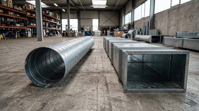
The choice between round and rectangular duct is a common design dilemma. Below is a comparison of the key features of both solutions:
| Feature | Round (spiro) | Rectangular |
|---|---|---|
Flow resistance | Lower | Higher (by 20-40%) |
Air tightness | Very good | Requires sealing |
Required installation space | Greater height | Smaller height |
Material cost | Lower | Higher |
Installation speed | Faster | Slower |
Acoustic insulation | Better | Worse (wall resonance) |
Dimensional flexibility | Stepped (standard range) | Any (in 50 mm increments) |
In most cases, round spiro ducts are preferred due to lower resistance, better air tightness and lower cost. Rectangular ducts are chosen primarily for spatial reasons.

Calculation Example - Round Duct
Let us assume we need to size a spiro duct for a supply section with an airflow of 500 m³/h in an office building (max. velocity 4.5 m/s).
Step 1: Determining the minimum cross-section
Minimum duct cross-sectional area:
Step 2: Determining the minimum diameter
Step 3: Selection from the standard range
The nearest larger standard diameter is 200 mm.
Step 4: Velocity verification
The velocity of 4.42 m/s is within the acceptable range for offices.
Step 5: Unit pressure drop
For a spiro duct (k = 0.1 mm) with a diameter of 200 mm and an airflow of 500 m³/h, the unit pressure drop is approximately 1.7 Pa/m. This value is typical and acceptable - the recommended range is 0.5-2.5 Pa/m.
All the above calculations can be performed automatically using our ventilation duct sizing calculator.
Calculation Example - Rectangular Duct
For the same airflow of 500 m³/h, we need to size a rectangular duct with a limited installation height of 250 mm.
Step 1: Fixing one dimension
We assume side B = 200 mm (leaving room for insulation).
Step 2: Determining the other side
We assume side A = 200 mm (rounding up to the nearest standard dimension in 50 mm increments).
Step 3: Verification
Duct 200 × 200 mm:
- Velocity:
- Hydraulic diameter:
- Aspect ratio: 1:1 (optimal)
The velocity of 3.47 m/s is comfortable and ensures a low noise level.
Typical Room Airflow Rates
When designing ventilation, the starting point is the required airflow. Below are the most commonly used values in accordance with the PN-83/B-03430 standard and Technical Requirements:
| Room | Required exhaust airflow |
|---|---|
Kitchen with window (gas cooker) | 70 m³/h |
Kitchen with window (electric cooker) | 50 m³/h |
Kitchen without window | 70 m³/h |
Bathroom | 50 m³/h |
WC | 30 m³/h |
Auxiliary room without window | 15 m³/h |
Living room (per person) | 30 m³/h |
Local Resistances - Fittings and System Components
In addition to linear losses in straight duct sections, local resistances generated by fittings occur in a ventilation system. These resistances are calculated using the formula:
where is the local resistance coefficient, dependent on the type of fitting.
Typical values of the coefficient:
| Component | Coefficient [-] |
|---|---|
90° elbow (round, smooth) | 0.15 - 0.30 |
90° elbow (rectangular, without turning vanes) | 1.10 - 1.30 |
90° elbow (rectangular, with turning vanes) | 0.15 - 0.25 |
Tee - straight flow | 0.10 - 0.50 |
Tee - branch | 0.50 - 1.50 |
Damper (open) | 0.10 - 0.20 |
Wall intake / exhaust terminal | 2.0 - 3.5 |
Supply diffuser | per manufacturer's data |
It is worth noting rectangular elbows without turning vanes - they generate several times higher resistance than round elbows. Installing turning vanes in rectangular elbows significantly reduces resistance.
Most Common Mistakes in Duct Sizing
1. Too narrow ducts in pursuit of savings - the designer selects a smaller cross-section to reduce material cost. As a result, pressure drops increase, requiring a more powerful (and more expensive) fan and generating higher noise.
2. Underestimating local resistances - in practice, resistances at fittings can account for 50-70% of the total system resistance. Omitting them from calculations leads to undersizing of the fan.
3. Using long sections of flexible ducts - flex ducts have many times higher roughness than rigid ducts. Even 2-3 metres of unstretched flex can generate resistance comparable to several tens of metres of spiro duct.
4. Ignoring the aspect ratio of rectangular ducts - ducts with proportions above 4:1 have significantly higher resistance and are prone to deformation. It is better to use two smaller ducts instead of one with extreme proportions.
5. No margin for regulation - sizing at the limit of maximum velocity leaves no margin for system regulation and possible future airflow adjustments.
Summary
Proper ventilation duct sizing requires consideration of the required airflow, permissible velocity, pressure drops and spatial conditions. Round spiro ducts should be the first choice due to better aerodynamic properties and lower cost. Rectangular ducts are used where limited installation space requires it.
To speed up your design work, use our ventilation duct sizing calculator, which automatically selects the round duct diameter or calculates the flow parameters for a rectangular duct with specified dimensions.
Back to articles list