
Gas pipe sizing - calculations, standards, and practical examples
7 kwietnia 2026 | Gas
Correct gas pipe sizing is the foundation of a safe and efficient installation. Undersized pipes cause excessive pressure drop and improper operation of gas appliances, while oversized pipes generate unnecessary costs. In small installations with a single appliance (e.g. a single-family home with a condensing boiler), a DN15 steel pipe is usually sufficient. However, for larger installations with multiple gas appliances and an extensive pipe network, detailed hydraulic calculations are necessary.
If you need to quickly size gas pipes, use our low-pressure gas installation calculator or medium and high pressure network calculator.
Basic concepts and principles
When calculating low-pressure gas installations (up to 5 kPa), the most important condition is ensuring adequate gas pressure at every appliance, especially the one most unfavorably located relative to the gas source. At the beginning of the installation, after the pressure regulator, there is a defined available pressure (typically 2,0-2,5 kPa). The designer's task is to select pipe diameters so that the pressure drop across the entire installation does not cause excessively low pressure at any gas appliance.
Available pressure and allowable pressure drop
Available pressure is the gas pressure at the outlet of the pressure regulator (or at the inlet to the internal installation). For low-pressure installations, it is typically 2,0-2,5 kPa (20-25 mbar). Each gas appliance has a specified operating pressure range, e.g. 1,3-2,5 kPa. The difference between the available pressure and the minimum pressure required by the appliance constitutes the allowable pressure drop in the installation.
In design practice, it is assumed that the total pressure drop in a low-pressure gas installation should not exceed 150-200 Pa (1,5-2,0 mbar). This value is significantly lower than theoretically allowable, providing a safety margin.
Pressure increase in vertical sections
An important phenomenon is the pressure increase of natural gas in upward vertical sections. Natural gas is lighter than air (relative density approx. 0,6), so for each metre of rise the gas pressure increases by 5,4 Pa. This phenomenon works in the designer's favour for installations supplying appliances on upper floors, as it compensates for part of the pressure losses caused by flow resistance.
When calculating the total pressure drop, this gain must be subtracted from the sum of linear and local losses:
Where is the height of rise in metres.
Calculating gas flow rate
The gas flow rate through the installation results directly from the capacity of the installed gas appliances. To determine the volumetric flow rate, divide the thermal capacity of the appliance by the calorific value of the gas:
Where:
- - volumetric gas flow rate [m³/h]
- - thermal capacity of the appliance [kW]
- - calorific value of the gas [kWh/m³]
For high-methane natural gas (group E), the calorific value is approx. 9,44 kWh/m³ (34 MJ/m³). For example, a 24 kW boiler consumes:
For quick flow conversions for different gases and units, the gas flow converter is useful.
Typical gas appliance capacities and gas consumption
The table below shows approximate capacities and gas flow rates for typical appliances in low-pressure installations:
| Gas appliance | Capacity [kW] | Gas flow rate [m³/h] |
|---|---|---|
Gas cooker (4-burner) | 8-10 | 0,85-1,06 |
Instantaneous DHW heater | 18-28 | 1,91-2,97 |
Single-function heating boiler | 15-30 | 1,59-3,18 |
Combi condensing boiler | 20-35 | 2,12-3,71 |
Gas unit heater | 10-50 | 1,06-5,30 |
Gas radiant heater | 5-40 | 0,53-4,24 |
Calculating pressure drop
The pressure drop in a low-pressure gas installation is calculated using the simplified Renouard formula:
Where:
- - pressure drop [daPa]
- - relative gas density (for gas E: 0,6) [-]
- - calculated section length [km]
- - volumetric gas flow rate [m³/h]
- - internal pipe diameter [cm]
To convert the result to Pa/m, multiply by 10 (converting daPa to Pa) and divide by the section length in metres.
This formula applies to turbulent flows, which is the typical case in gas installations. Based on it, the unit pressure drop (Pa/m) can be calculated and compared with the allowable value.
Pipe sizing - recommended values
The table below shows approximate flow ranges for standard steel pipe sizes:
| Nominal diameter | Internal dia. [mm] | Max. flow rate [m³/h] | Typical application |
|---|---|---|---|
| DN15 (1/2") | 16,1 | ~2,5 | Single appliance up to 24 kW |
| DN20 (3/4") | 21,7 | ~5,0 | Boiler + cooker |
| DN25 (1") | 27,2 | ~10,0 | Header sections, small buildings |
| DN32 (1 1/4") | 36,0 | ~20,0 | Multi-family buildings |
| DN40 (1 1/2") | 41,9 | ~30,0 | Gas risers |
| DN50 (2") | 53,1 | ~55,0 | Main supply pipes |
Maximum flow values are given for a unit pressure drop of approx. 10 Pa/m. Final sizing requires verifying that the flow velocity does not exceed 6 m/s on the most loaded section (K. Bąkowski, "Sieci i instalacje gazowe").
Local losses - equivalent lengths
In addition to linear losses (on straight sections), gas installations experience local losses at fittings, valves, and other hardware. These are most commonly accounted for using the equivalent length method - each fitting is replaced by an equivalent length of straight pipe of the same diameter. The table below contains equivalent lengths (in metres) for typical fittings:
| Type of local resistance | DN10 | DN15 | DN20 | DN25 | DN32 | DN40 | DN50 | DN65 |
|---|---|---|---|---|---|---|---|---|
| Ball valve | 0,10 | 0,15 | 0,20 | 0,30 | 0,40 | 0,50 | 0,60 | 0,80 |
| Angle valve | 0,30 | 0,40 | 0,70 | 0,80 | 1,00 | 1,70 | 2,00 | 3,00 |
| Elbow | 0,40 | 0,50 | 1,30 | 1,30 | 1,50 | 1,50 | 1,70 | 1,70 |
| Reducer | - | 0,20 | 0,40 | 1,20 | 1,20 | 1,60 | 1,60 | - |
| Through tee | 0,10 | 0,40 | 0,40 | 0,50 | 0,60 | 0,90 | 1,30 | 1,80 |
| Branch tee | 0,25 | 0,40 | 0,90 | 1,10 | 1,40 | 1,90 | 2,70 | 4,50 |
In simplified calculations, instead of counting individual fittings, local losses are assumed to be 20-30% of linear losses. This is acceptable in installations with a simple configuration.
Gas pipe materials
The choice of pipe material depends on the installation location and is strictly regulated.
Internal installations
Inside buildings, gas pipes are made exclusively from steel pipes (black or galvanised) joined by welding. Threaded connections are only permitted where welding is not possible (e.g. when installing valves). Steel pipes are used in accordance with PN-EN 10255 (welded pipes) or PN-EN 10216 (seamless pipes).
Copper pipes (PN-EN 1057) are also permitted in internal installations with pressure up to 5 kPa, provided they are hard or semi-hard with a wall thickness of at least 1 mm. Connections are made by brazing.
External installations (service connections, networks)
Gas service connections and distribution networks laid underground are most commonly made from PE pipes (polyethylene) designated PE100 SDR11 or SDR17,6 in accordance with PN-EN 12007. PE pipes are joined by butt fusion or electrofusion welding. At the transition from PE to steel (before entering the building), PE/steel transition fittings are used.
PE pipes must not be installed inside buildings or above ground level (sensitivity to UV radiation and mechanical damage).
Gas meter and pressure regulator
Gas meter selection
The gas meter is selected based on the maximum gas flow rate calculated from the total capacity of all gas appliances, taking into account the simultaneity factor (not all appliances operate at full capacity at the same time). The maximum flow rate of the gas meter (Qmax) must be greater than or equal to the calculated flow rate. At the same time, the minimum flow rate (Qmin) must ensure accurate measurement when the smallest appliance is operating.
Typical diaphragm gas meters used in residential installations:
- G4 - Qmax = 6 m³/h - for individual apartments (boiler + cooker)
- G6 - Qmax = 10 m³/h - for apartments with higher consumption
- G10 - Qmax = 16 m³/h - for single-family homes with a large boiler
- G16 - Qmax = 25 m³/h - for small multi-family buildings
- G25 - Qmax = 40 m³/h - for multi-family buildings
Pressure regulator
The pressure regulator reduces gas pressure from the network level (medium pressure, typically 100-400 kPa) to the operating pressure of the internal installation (low pressure, 2,0-2,5 kPa). It is selected based on the maximum flow rate and the required outlet pressure. The regulator must have a safety valve (relief valve) protecting the installation against excessive pressure rise in the event of a failure.
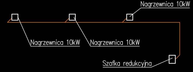
Practical example - step by step
Let us analyse the calculations for a gas installation in a small hall with three gas unit heaters, each rated at 15 kW.
Input data
- 3 gas unit heaters, capacity: 15 kW each
- Pressure after regulator: 2,5 kPa (from connection conditions)
- Minimum pressure required by the heaters: 2,0 kPa (from the data sheet)
- Allowable pressure drop: 2,5 - 2,0 = 0,5 kPa = 500 Pa (but we assume max. 200 Pa)
- High-methane natural gas E, Wd = 9,44 kWh/m³
Step 1: Calculating flow rates
Gas flow rate for one heater:
Flow rates on individual sections of the installation:
- Section III (from the junction to the last heater): 1,59 m³/h (15 kW)
- Section II (from the first junction to the second): 3,18 m³/h (30 kW)
- Section I (from the regulator to the first junction): 4,77 m³/h (45 kW)
Step 2: Pipe sizing
Using the low-pressure gas installation calculator, we enter the flow rates and read the proposed diameters:
- 15 kW (1,59 m³/h) - DN15 - unit pressure drop: 4,95 Pa/m
- 30 kW (3,18 m³/h) - DN20 - unit pressure drop: 5,41 Pa/m
- 45 kW (4,77 m³/h) - DN25 - unit pressure drop: 3,41 Pa/m
Step 3: Calculating linear losses
We assume section lengths: each horizontal section is 10 m, and the riser is 4 m. Section I is 14 m (10 m horizontal + 4 m riser), Section II is 10 m, Section III is 10 m.
Step 4: Accounting for local losses
As a simplification, we assume local losses at 20% of linear losses:
Step 5: Accounting for pressure increase in the riser
Over the 4-metre riser, gas pressure increases by:
Step 6: Total pressure drop
The total pressure drop is 160 Pa, which is less than the allowable 200 Pa. The selected diameters meet the requirements.
Gas meter selection
The total gas flow rate is 4,77 m³/h. A G6 gas meter (Qmax = 10 m³/h) is appropriate, providing flow capacity reserve and accurate measurement when only one heater is operating.
Standards and regulations
The design and construction of gas installations in Poland is governed by the following documents:
- PN-EN 1775 - Gas supply. Gas pipework for buildings. Maximum operating pressure up to 5 bar. Functional recommendations
- PN-M-34507 - Gas installations for gaseous fuels using copper pipes. Technical requirements
- Regulation of the Minister of Infrastructure on technical conditions to be met by buildings and their location (Dz.U. 2019 item 1065, as amended) - Part IV, Chapter 7: Gas installation
- PN-EN 12007 - Gas infrastructure. Pipelines for maximum operating pressure up to 16 bar
- PN-EN 10255 - Non-alloy steel tubes suitable for welding and threading
The designer must hold appropriate building qualifications in the installation specialisation covering heating, ventilation, gas, water supply, and sewage networks, installations, and equipment.
Gas installation safety
Natural gas is a flammable and explosive fuel, therefore special safety rules must be observed when designing and constructing gas installations:
- Tightness - the installation must be gas-tight. After completion, a tightness test is carried out at 5 kPa (50 mbar) pressure for low-pressure installations. The pressure drop over 30 minutes must not exceed 0,1 kPa
- Ventilation - rooms with gas appliances must have adequate ventilation (supply and exhaust)
- Flue gas discharge - every gas appliance with an open combustion chamber must be connected to a chimney flue
- Gas detectors - in public utility rooms, installation of gas detectors is recommended
- Marking - gas pipes are marked in yellow
- Clearances - gas pipes must maintain required distances from electrical, water, and other installation pipes
- Shut-off valves - a shut-off valve (gas cock) must be installed before each gas appliance and on each riser
Summary
Gas pipe sizing requires consideration of many factors: gas flow rate resulting from appliance capacities, allowable pressure drop, linear and local losses, as well as the phenomenon of pressure increase in risers. For simple installations with a single appliance, a DN15 pipe is usually sufficient. For larger installations, detailed hydraulic calculations are essential.
A correctly sized gas installation ensures the safe and efficient operation of all gas appliances. Remember to comply with applicable standards and regulations and to perform a tightness test after installation is complete.
Size gas pipes using the low-pressure gas installation calculator or the medium/high pressure network calculator. To convert flow rates between different units and conditions, use the gas flow converter.
Back to articles list