
Low-pressure LPG installation — pipe sizing (propane and propane-butane mix)
29 maja 2026 | Gas
An LPG (liquefied petroleum gas) installation supplied from a domestic tank or a cylinder bank is, for many homes beyond the reach of the natural gas grid, the only alternative to oil or pellets. At the heart of every such project is the sizing of the pipes. A pipe that is too narrow causes excessive pressure drop and unstable operation of the boiler or cooker; one that is too wide needlessly raises costs. Unlike natural gas, LPG is heavier than air and has completely different physical properties, which directly affect the calculations.
If you want to quickly size the pipes for your installation, use the low-pressure LPG installation calculator — it accounts for both types of fuel, three pipe materials, and fitting resistances.
What is a low-pressure LPG installation
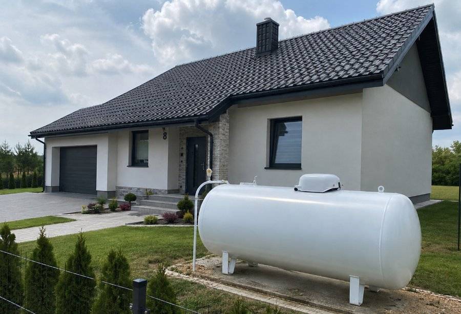
Liquefied petroleum gas is stored in a tank or cylinder under a pressure of several bar in the liquid phase. It reaches the appliances, however, as a gas at a significantly reduced pressure. In domestic installations the reduction is most often carried out in two stages:
- Stage I — the regulator at the tank lowers the pressure to about 0,7–1,5 bar (intermediate pressure),
- Stage II — the regulator before the entry into the building sets the operating pressure of the low-pressure installation.
The nominal supply pressure for appliances is 37 mbar (3,7 kPa) for propane and the propane-butane mix and 30 mbar for pure butane. It is precisely the section downstream of the stage II regulator — from the building entry up to the cocks at the appliances — that is the subject of the hydraulic calculations described in this article.
Allowable pressure drop
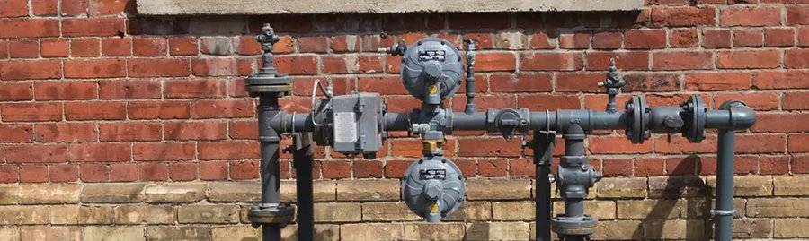
The designer's task is to size the pipes so that the pressure at the most unfavorably located appliance does not fall below the value required by that appliance. In practice, for low-pressure LPG installations it is assumed that the pressure drop in the internal installation should not exceed about 2,5 mbar (250 Pa). This leaves a safe margin relative to the nominal 37 mbar and the appliances' tolerances.
Low-pressure LPG vs natural gas — key differences
Although the calculation method is similar, LPG differs from natural gas (group E) on three important fronts:
- Operating pressure — 37 mbar for LPG versus 20–25 mbar for low-pressure natural gas.
- Calorific value — LPG has a calorific value several times higher per m³, so for the same capacity a much smaller volumetric flow rate is needed.
- Density relative to air — this is the difference with the greatest consequences. Natural gas is lighter than air, LPG is heavier. This affects both the calculation of risers and the safety rules (see below).
If you are designing an installation for mains gas, the right tool will be the low-pressure natural gas installation calculator. For networks supplying larger facilities, the medium and high pressure network calculator is the way to go.
Technical propane vs 60/40 propane-butane mix
In Polish conditions, two basic fuels are encountered. Technical propane dominates in tank installations because it vaporises even at sub-zero temperatures (boiling point about −42 °C) and performs well throughout the winter. The 60/40 mix (60% propane, 40% butane) is typical for cylinders, but butane stops vaporising at around 0 °C, so in winter its effectiveness as a gas phase declines.
Differences in density, viscosity, and calorific value directly affect the flow resistance and the pipe sizing. The table below lists the parameters used in the calculations:
| Parameter | Technical propane | 60/40 mix |
|---|---|---|
Gas density [kg/m³] | 1,90 | 2,15 |
Kinematic viscosity [m²/s] | 4,22 · 10⁻⁶ | 3,64 · 10⁻⁶ |
Calorific value [kWh/m³] | 26,7 | 27,8 |
The mix is denser and has a higher calorific value — for the same appliance capacity it requires a slightly smaller volumetric flow rate, but it generates larger losses arising from its density. That is why, when sizing pipes, it is always worth specifying the correct fuel in the calculations.
What affects pipe sizing
The final choice of pipe cross-section depends on several factors that the calculator analyses simultaneously:
- Flow rate (or appliance capacity) — the greater the demand, the larger the required diameter.
- Installation length — a longer route increases the total pressure drop.
- Pipe material and its roughness — steel, copper, and polyethylene differ in wall smoothness, which affects friction resistance.
- Allowable pressure drop — the limit value that must not be exceeded.
- Gas velocity — limited to 6 m/s to avoid noise and wall erosion.
Absolute roughness of materials
Each material has a different smoothness of its internal wall, described by the absolute roughness ε. The lower the value, the lower the friction resistance:
Steel | 0,15 mm |
|---|---|
Copper | 0,0015 mm |
Polyethylene (PE) | 0,007 mm |
Why we limit gas velocity to 6 m/s
Exceeding a velocity of 6 m/s leads to bothersome noise (whistling in the pipes) and accelerated erosion of the walls, especially at elbows. Importantly, flow resistance grows with the square of the velocity — doubling the velocity means a fourfold larger pressure drop. That is why staying within the limit is not only a matter of acoustic comfort, but also of the installation's energy economy.
How pressure drop is calculated
The unit pressure drop (per metre of pipe) is determined from the Darcy-Weisbach equation:
Where:
- — gas density [kg/m³]
- — friction factor [-]
- — internal pipe diameter [m]
- — flow velocity [m/s]
The character of the flow is determined by the Reynolds number:
where is the kinematic viscosity of the gas. The friction factor depends on the flow regime:
- for laminar flow (): ,
- for turbulent flow () — from the Colebrook-White equation:
In gas installations the flow is almost always turbulent, and the Colebrook-White equation is implicit — it requires an iterative solution. Working this out by hand for each section, with several elbows and tees, is dozens of minutes of work and a real risk of error. The LPG installation calculator performs a full iteration for each proposed diameter in a fraction of a second.
Equivalent length of fittings
Pressure drop arises not only on straight sections (linear losses), but also at fittings and hardware — elbows, tees, reducers, and cocks (local losses). They are most conveniently accounted for using the equivalent length method: each element is replaced by an equivalent length of straight pipe of the same diameter that generates the same resistance.
Below are indicative equivalent lengths for copper pipes in typical domestic sizes:
| Element | 15×1 | 18×1 | 22×1 |
|---|---|---|---|
| Elbow 90° | 0,40 | 0,50 | 0,60 |
| Ball valve | 0,15 | 0,20 | 0,25 |
| Tee (through) | 0,30 | 0,40 | 0,50 |
The practical conclusion is this: a straight route 15 m long with a few elbows and cocks can have a calculated length close to 20 m. Omitting fittings is one of the most common reasons for underestimating pressure drop. The calculator lets you enter the number of individual fittings and automatically adds their equivalent length.
Risers with LPG — watch the density
Because LPG is heavier than air, in upward risers the gas pressure decreases (the opposite of natural gas, where it increases). The drop is about 7 Pa per metre of rise for propane and about 9 Pa/m for the mix. This loss must be added to the sum of resistances when the appliance is located above the point where gas enters the building.
Converting appliance capacity into flow rate
The gas flow rate follows directly from the capacity of the installed appliances. To determine it, we divide the thermal capacity by the calorific value of the fuel:
Where is the capacity [kW] and is the calorific value [kWh/m³]. For propane , for the mix . For example, a 24 kW boiler running on propane draws m³/h. The flow rate can also be expressed in kg/h by multiplying the volume by the gas density — in the LPG industry kilograms are often used.
| Appliance | Capacity [kW] | Flow rate [m³/h] | Consumption [kg/h] |
|---|---|---|---|
| Gas cooker (4-burner) | 8–9 | 0,30–0,34 | 0,57–0,65 |
| Combi condensing boiler | 20–24 | 0,75–0,90 | 1,42–1,71 |
| Single-function heating boiler | 15–30 | 0,56–1,12 | 1,07–2,13 |
| Instantaneous DHW heater | 18–28 | 0,67–1,05 | 1,28–1,99 |
| Gas radiant / unit heater | 5–40 | 0,19–1,50 | 0,36–2,85 |
The values are given for propane ( kWh/m³, density 1,90 kg/m³). When designing, you must also account for the simultaneity factor — rarely do all appliances operate at full capacity at once.
Vaporisation capacity of the source
Sizing the pipes is only half the task. The other half is checking whether the source can keep up with vaporising the gas. The gas-phase output of a tank or cylinder depends on the surface wetted by the liquid, the fill level, and the ambient temperature. In winter, with a low gas level in a cylinder, the vaporisation capacity can drop drastically — even the best-sized pipe will not help if the appliance does not receive a sufficient amount of the gas phase.
Practical example — step by step
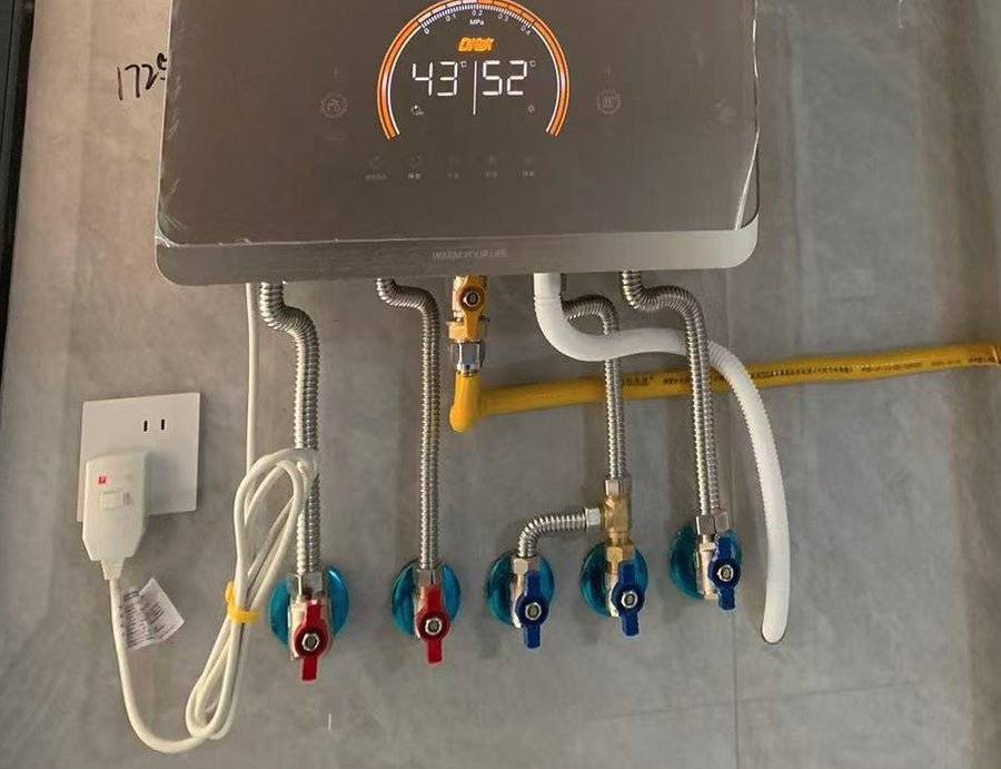
Let us consider a single-family home supplied with propane from a domestic tank. The appliances: a 9 kW gas cooker and a 24 kW condensing boiler. The internal installation is made of copper pipe.
Step 1: Flow rates
- Boiler: m³/h
- Cooker: m³/h
- Main section (both appliances): m³/h
Step 2: Pipe sizing
By entering the flow rates into the LPG installation calculator (fuel: propane, material: copper), we read off the proposed diameters and their parameters:
- 1,24 m³/h (main section) → copper 18×1 — velocity about 1,7 m/s, unit drop about 6 Pa/m
- 0,90 m³/h (to the boiler) → copper 15×1 — velocity about 1,9 m/s
- 0,34 m³/h (to the cooker) → copper 12×1 — velocity about 1,2 m/s
All velocities are below the 6 m/s limit.
Step 3: Calculated length of the main section
Let us assume 12 m of straight 18×1 section plus the hardware: 3 elbows, 1 ball valve, 1 through tee. From the equivalent length table:
Step 4: Losses on the main section
Step 5: Correction for the riser
The boiler is located 3 m above the gas entry. Because propane is heavier than air, in an upward riser the pressure decreases — we add the loss:
Step 6: Total drop
The total drop (about 106 Pa) is clearly lower than the allowable 250 Pa — the selected diameters meet the requirements, with a reserve for expansion. The exact values for your configuration are best checked directly in the LPG installation calculator, which will calculate the drop for all sections and fittings at once.
Most common mistakes
- Omitting fittings — counting only the length of straight sections underestimates the pressure drop by as much as several dozen percent.
- Confusing the fuel — propane and the mix have different density and calorific value; calculations for the wrong gas give an incorrect flow rate and resistances.
- Mishandling risers — with LPG, upward risers are an additional loss, not a gain as with natural gas.
- Exceeding 6 m/s — results in noise and a quadratic increase in losses.
- Confusing units — mbar, kPa, and Pa are easy to mix up (1 mbar = 100 Pa = 0,1 kPa).
- Running pipes in rooms below ground level — see safety.
Safety and materials
The most important rule arising from the physics of LPG: a gas heavier than air accumulates at the floor, in hollows, ducts, and cellars. For this reason, LPG installations must not be run in rooms and spaces located below ground level without adequate ventilation, in ducts, or in manholes where a dangerous explosive mixture could form.
For the same reason, rooms with liquefied petroleum gas appliances must have exhaust ventilation with an opening right at the floor — this is an important distinguishing feature compared with natural gas, where the exhaust is placed below the ceiling because natural gas rises upward.
Regarding materials:
- Inside the building — steel pipes (joined by welding) or copper pipes (joined by hard soldering / brazing, a filler metal with a melting point above 450 °C).
- Outside / underground — the service connection from the tank is run with a PE pipe joined by fusion welding; PE must not be run inside buildings or above ground (sensitivity to UV and mechanical damage). The PE terminates in the ground, and the exit onto the building wall is made through a PE/steel transition — the approach to the main cock is then run with a steel pipe.
The design and construction of liquefied petroleum gas installations are governed, among others, by: PN-EN 1775 (gas pipework in buildings), the Regulation of the Minister of Infrastructure on the technical conditions to be met by buildings and their location — the Technical Conditions Regulation (WT) (Section IV, Chapter 7 — liquefied petroleum gas installations, including the required tank clearances), and the standards concerning low-pressure regulators for LPG (PN-EN 16129). After the installation is built, a tightness test is mandatory.
Summary
Sizing low-pressure LPG installation pipes relies on the same hydraulic principles as natural gas, but it requires accounting for the different properties of liquefied gas: a higher operating pressure (37 mbar), a higher calorific value, and — above all — a greater density than air, which changes the gas's behaviour in risers and imposes strict safety rules. Remember to distinguish between propane and the mix, to add the equivalent length of fittings, and to keep the velocity below 6 m/s.
Instead of manually solving the Colebrook-White equation for each section, size the pipes in the low-pressure LPG installation calculator — you specify the fuel, material, and fittings, and the tool proposes optimal diameters together with the pressure drop and flow velocity. For quickly converting flow rates between units, the gas flow converter will come in handy.
Back to articles list