
Water Supply Pipe Sizing — calculations, standards and practical example
7 kwietnia 2026 | Water Supply
Correct pipe sizing is one of the key stages in designing an internal water supply installation. A diameter that is too small causes insufficient pressure at the most remote draw-off points, noise in the pipes and accelerated wear of fittings. Oversizing the installation, on the other hand, means higher material costs, longer waiting times for hot water and a greater risk of water stagnation in the pipes.
If you want to quickly calculate diameters for your installation, use our water supply pipe sizing calculator. Below we discuss in detail the calculation method, standards, pipe materials and common design mistakes.
Standard PN-92/B-01706 — the basis of calculations
The primary document governing the design of water supply installations in buildings is the Polish standard PN-92/B-01706 "Water Supply Installations — Design Requirements". Although formally superseded by European standards of the PN-EN 806 series, in design practice it remains the main calculation tool in Poland.
This standard defines:
- normative outflows for individual sanitary fixtures,
- design flow formulas depending on the building type and the sum of normative outflows,
- velocity criteria for water flow in different types of pipes,
- pressure requirements at draw-off points (minimum 0.05 MPa for most fittings).
It is supplemented by standard PN-EN 806-3, which provides general principles for installation sizing, and DIN 1988, used alternatively for installations designed according to German standards.
Normative outflows of sanitary fixtures
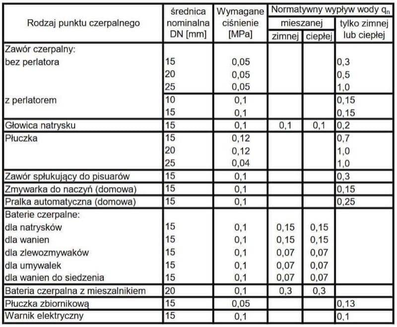
The first calculation step is to list all sanitary fixtures supplied by a given pipe section. Each fixture has an assigned normative outflow expressed in dm³/s. These values are derived from the PN-92/B-01706 standard and reflect typical usage conditions.
| Sanitary fixture | [dm³/s] |
|---|---|
Washbasin | 0,07 |
Kitchen sink | 0,07 |
Shower | 0,15 |
Bathtub | 0,15 |
Bidet | 0,07 |
Cistern flush valve (WC) | 0,13 |
Pressure flush valve (WC) | 1,00 |
Automatic washing machine | 0,25 |
Dishwasher | 0,15 |
Draw-off valve DN 15 | 0,15 |
Draw-off valve DN 20 | 0,25 |
For each installation section, the sum of normative outflows is calculated:
Design flow
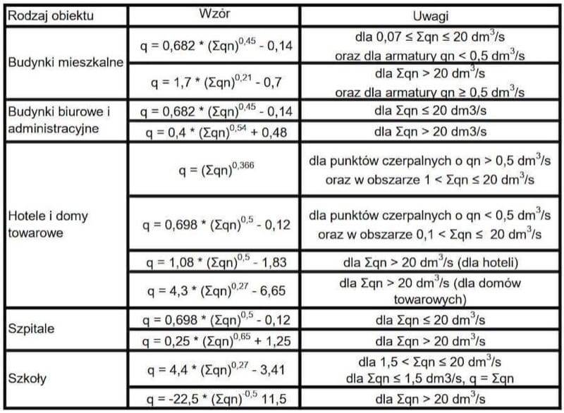
The sum of normative outflows is not directly the design flow — not all fixtures operate simultaneously. The PN-92/B-01706 standard introduces a simultaneity factor for fixture operation, which is built into the design flow formulas.
For residential buildings the standard provides the following formulas depending on the value of :
- dm³/s:
- dm³/s:
- dm³/s:
For public, office and communal residential buildings different sets of formulas are used, also depending on the range of . Details are given in the standard.
Pipe diameter selection
Knowing the design flow , we select the pipe diameter so that the water flow velocity does not exceed the permissible values. The internal pipe diameter is determined from the continuity equation:
where:
- — internal pipe diameter [m],
- — design flow [m³/s],
- — permissible flow velocity [m/s].
After calculating the minimum internal diameter, the nearest larger commercial pipe size for the given material is selected, and then the actual flow velocity is checked.
Flow velocity criteria
Standards PN-92/B-01706 and DIN 1988 specify maximum water flow velocities depending on the type of pipe:
| Pipe type | PN-92/B-01706 [m/s] | DIN 1988 [m/s] |
|---|---|---|
Connections from riser to draw-off points | 1,5 | 2,0 |
Risers in water supply installations | 1,5 | 2,0 |
Distribution pipes | 1,0 | 1,5 |
Water supply connections (service pipes) | 1,0 | 1,5 |
Exceeding the permissible velocity causes increasing hydraulic noise, greater pressure losses and accelerated erosion of the pipe inner surface. In practice it is recommended to design with a velocity of 0.8–1.2 m/s in risers and branches, which ensures acoustic comfort and reasonable pressure losses.
Pipe materials for water supply installations
The choice of pipe material directly affects diameter selection — for the same outer diameter, different materials have different wall thicknesses and therefore different internal diameters.
PEX pipes (cross-linked polyethylene)
The most popular material in domestic installations. PEX pipes are flexible, easy to install and corrosion-resistant. Joined with press fittings or sliding sleeve fittings. Available in coils, which minimises the number of joints.
PP pipes (polypropylene)
PP pipes are joined by polyfusion (welding). They have a large wall thickness, which means a relatively small internal diameter for a given outer diameter. Durable and inexpensive, but rigid — they require more fittings.
Copper pipes
A traditional material with excellent bacteriostatic properties. The thin wall provides a large internal diameter. Joined by soldering or pressing. The higher material cost is compensated by durability and hygiene.
Multilayer pipes (PEX-Al-PEX)
These combine the advantages of plastic and metal pipes. The aluminium layer gives the pipe its shape and limits thermal expansion. Popular in domestic hot water installations.
The table below compares typical commercial pipe dimensions for different materials along with their internal diameters:
| Material | Outer dim. x wall [mm] | Internal dia. [mm] |
|---|---|---|
PEX | 16 x 2,0 | 12,0 |
PEX | 20 x 2,0 | 16,0 |
PEX | 25 x 2,5 | 20,0 |
PEX | 32 x 3,0 | 26,0 |
PP PN20 | 20 x 3,4 | 13,2 |
PP PN20 | 25 x 4,2 | 16,6 |
PP PN20 | 32 x 5,4 | 21,2 |
PP PN20 | 40 x 6,7 | 26,6 |
Copper | 15 x 1,0 | 13,0 |
Copper | 18 x 1,0 | 16,0 |
Copper | 22 x 1,0 | 20,0 |
Copper | 28 x 1,5 | 25,0 |
It is clearly visible that a PP 25 mm pipe (internal diameter 16.6 mm) will carry significantly less water than a PEX 25 mm pipe (internal diameter 20.0 mm) or a copper 22 mm pipe (internal diameter 20.0 mm) at the same flow velocity. This is a common source of errors — the designer assumes "diameter 25" without considering material differences.
Practical example — a detached house with two bathrooms
Let us consider a two-storey detached house with the following sanitary fixtures:
Ground floor:
- kitchen: kitchen sink ( = 0,07), dishwasher ( = 0,15)
- bathroom: washbasin ( = 0,07), WC with cistern flush ( = 0,13), shower ( = 0,15)
- utility room: washing machine ( = 0,25), draw-off valve DN 15 ( = 0,15)
First floor:
- bathroom: washbasin ( = 0,07), WC with cistern flush ( = 0,13), bathtub ( = 0,15), bidet ( = 0,07)
Step 1 — Sum of normative outflows
We add up all normative outflows:
Step 2 — Design flow
For a residential building with dm³/s we use the formula:
Step 3 — Distribution pipe diameter
We assume a permissible velocity for the distribution pipe = 1,0 m/s. We convert the flow to m³/s:
We calculate the minimum internal diameter:
We select a pipe:
- PEX 32 x 3,0 — internal diameter 26.0 mm. Checking velocity: m/s. Exceeds 1.0 m/s for a distribution pipe — too small.
- PEX 40 x 3,7 — internal diameter 32.6 mm. Velocity: m/s. Condition met.
Alternatively in copper: Cu 28 x 1,5 (di = 25 mm, = 1,33 m/s — too high) or Cu 35 x 1,5 (di = 32 mm, = 0,81 m/s — OK).
Step 4 — Riser supplying the first floor
The first floor has: washbasin, WC, bathtub, bidet. Sum dm³/s.
Design flow: dm³/s.
For the riser (permissible velocity 1,5 m/s):
We select PEX 25 x 2,5 (di = 20 mm). Velocity: m/s. Condition met with margin.
Step 5 — Branch to a single fixture
Branch to the shower ( = 0,15 dm³/s, = 0,15 dm³/s — single fixture, no reduction):
We select PEX 16 x 2,0 (di = 12 mm). Velocity: m/s — within the 1,5 m/s limit.
All calculations for such a building can be performed automatically with our pipe sizing calculator, which calculates each section individually and proposes appropriate commercial pipe sizes.
Domestic hot water circulation
In buildings where the distance from the hot water source (boiler, water heater) to the most remote draw-off point exceeds a few metres, the problem of long waiting times for hot water arises. The solution is a DHW circulation system — an additional return pipe through which cooled water returns to the heat source.
Circulation affects pipe sizing as follows:
- The circulation pipe is sized based on the heat losses of the supply pipes, not on normative outflows. Typical diameters are PEX 16 or PEX 20.
- The DHW supply pipe must have the same diameter as the corresponding cold water pipe (because it serves the same fixtures).
- The circulation pump is sized based on the circulation flow rate and the hydraulic resistance of the loop.
According to the current Polish Technical Conditions, circulation is required when the water volume in the pipes from the heater to the most remote draw-off point exceeds 3 dm³. In practice this applies to most detached houses with a central water heater.
It is worth noting that circulation forces a constant water flow in the installation, which eliminates the problem of stagnation but increases heat losses. Therefore circulation pipes should be well insulated thermally.
Most common pipe sizing mistakes
Mistake 1 — Comparing diameters without considering the material
A PP 25 mm pipe has an internal diameter of only 16.6 mm, while PEX 25 mm has 20.0 mm. The difference in cross-sectional area is over 45%. A designer who changes the material without recalculating may end up with an installation with completely different hydraulic parameters.
Mistake 2 — Ignoring pressure losses in fittings
The pipe diameter alone is not everything. Every valve, elbow, tee and filter causes additional pressure losses. In an extensive installation, local losses can account for 30–50% of the total losses. They must be taken into account when verifying whether the pressure at the most remote draw-off point is sufficient (min. 0.05 MPa).
Mistake 3 — Failing to account for available pressure
Pipe sizing must consider the available pressure in the water supply network. If the pressure at the service connection is only 0.25 MPa and the building has an upper floor (pressure loss due to height approx. 0.05 MPa per storey), the margin for linear and local losses is very small. In such cases larger diameters or a booster pump set must be used.
When designing a water supply connection, our water supply connection and network calculator is helpful — it accounts for pressure losses along the pipe length.
Mistake 4 — Oversizing the installation
Excessively large diameters are not just more expensive. In a hot water installation, oversizing means a larger volume of water in the pipes, longer waiting times for hot water and greater heat losses. For cold water it means longer stagnation of water in the pipes, which at higher ambient temperatures favours the growth of Legionella bacteria.
Mistake 5 — Sizing "by eye" without calculations
The common practice of "PEX 20 for branches, PEX 25 for risers, PEX 32 for the manifold" may work in a small flat, but in a house with several bathrooms or a multi-family building it leads to serious pressure and flow problems.
Summary
Correct water supply pipe sizing requires a systematic approach: from listing the fixtures, through calculating flows, to selecting diameters considering the pipe material and velocity criteria. Standard PN-92/B-01706 provides a proven calculation methodology which — despite the passage of years — remains the primary tool for sanitary installation designers in Poland.
Key principles:
- Always start by listing the fixtures and calculating ,
- Apply the appropriate design flow formulas for the building type,
- Consider the internal diameter of the pipe, not the outer diameter,
- Check the velocity criterion for each type of pipe,
- Verify the available pressure at the most remote draw-off points.
All these calculations can be performed quickly and accurately with our water supply pipe sizing calculator. Simply enter the number and type of sanitary fixtures, and the calculator will compute the flows and select the pipe diameters.
Back to articles list