
Safety valve selection in heating systems – standards, calculations, practice
1 kwietnia 2026 | Heating
A safety valve is a component that a designer hopes never to think about in terms of its activation — but must always think about in terms of its selection. A correctly selected valve is the last line of defence: a device that, in the event of a regulation failure, loss of flow or loss of control over the heat source, prevents a catastrophic pressure increase in the system. Incorrect selection — whether undersized or oversized — can lead to equipment damage, threats to human health and life, and at best to the rejection of documentation by the Office of Technical Inspection (UDT).
If you want to quickly and correctly select a safety valve for a boiler or heat substation, use our safety valve selection calculator.
Legal and normative basis
Safety valve selection in heating systems is not a matter of experience or intuition — it is strictly regulated by standards and regulations. The designer must take into account the requirements arising from several key documents:
- Pressure Equipment Directive PED 2014/68/EU — European regulation on pressure equipment, defining essential safety requirements.
- PN-B-02414:1999 — Polish standard "Heating. Protection of closed-system water heating installations with diaphragm expansion vessels". This is the primary document for heating system designers in Poland.
- PN-EN 12828 — European standard for the design of water-based heating systems in buildings.
- PN-EN ISO 4126-1 — harmonised standard for safety devices against excessive pressure, defining design and calculation requirements for safety valves.
- WUDT-UC-WO-O — Conditions of the Office of Technical Inspection, specifying detailed technical requirements for pressure equipment subject to inspection.
Selection "by eye" — for example based solely on the boiler connection diameter — is a methodological error. The connection diameter says nothing about the required valve capacity, which depends on the heat source output, set pressure, discharge coefficient and the physical properties of the medium.
Physical phenomena in emergency situations
To understand why safety valve selection requires precise calculations, one must understand the physical phenomena occurring in the system under emergency conditions.
Steam production in boilers
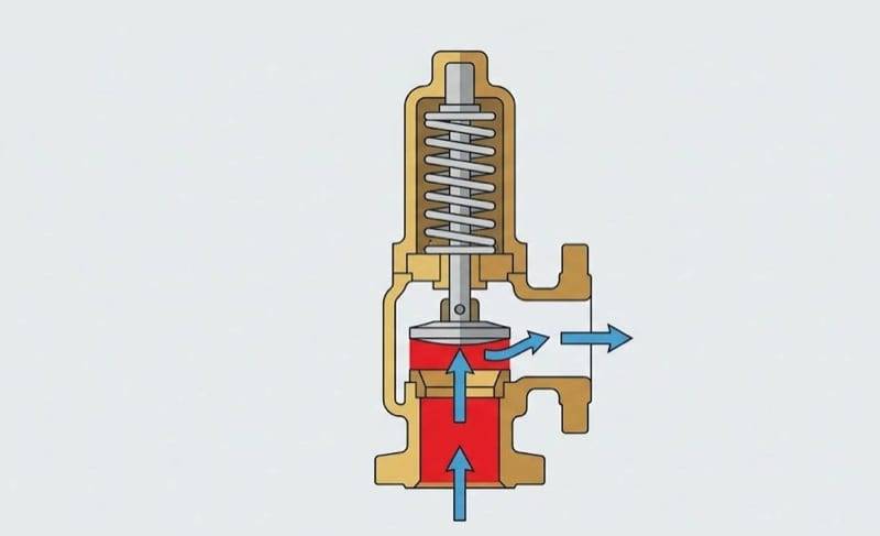
When a boiler is operating and heat extraction is interrupted (e.g. circulation pump failure, valve closure), all the boiler's thermal output accumulates in the boiler water. The water temperature rises, and upon reaching the saturation temperature corresponding to the system pressure, boiling begins. The resulting steam has a volume several hundred times greater than the liquid from which it was formed — and it is precisely this rapid evaporation that constitutes the main hazard. The safety valve must be capable of discharging all steam production resulting from the boiler output.
Volumetric expansion
Even before reaching the boiling point, a rise in water temperature causes volumetric expansion. In a closed system without a functioning expansion vessel, this volume increase translates directly into a pressure increase. The safety valve is the last barrier protecting the system.
"Tube Rupture" scenario — heat exchanger failure in a heat substation
In heat substations supplied from a district heating network, there is an additional hazard specific to heat exchangers. If a tube rupture occurs in the exchanger (a so-called double ended rupture), the medium from the network circuit at a pressure of around 5–10 bar can penetrate the internal system, designed for a pressure of 3 bar. The pressure difference is large enough that the internal system can suffer serious damage within a fraction of a second.
The key distinction here is between exchanger types:
- Shell-and-tube (JAD) exchangers — have tubes of a defined internal diameter. In a failure scenario, the leak can be calculated based on the double tube cross-section and the pressure difference.
- Plate exchangers — do not have individual tubes; the flow channels are formed by plate profiles. The failure scenario is more complex, but the calculation method is based on analogous principles.
Key selection parameters
Correct safety valve selection requires knowledge of several physical and catalogue parameters. Each of them has a significant impact on the calculation result.
Set pressure ()
The set pressure is the pressure at which the valve begins to open. It represents the safety limit for the protected device. It must not exceed the maximum allowable working pressure of the boiler or system. This value is derived from the technical documentation of the heat source.
Discharge coefficient ( / )
The discharge coefficient determines the actual capacity of the valve relative to the ideal capacity. It is a catalogue parameter from the manufacturer, confirmed by testing. We distinguish two main valve types:
| Parameter | Spring-loaded valve | Diaphragm valve |
|---|---|---|
Typical range | 0,4–0,7 | 0,3–0,5 |
Application | Boilers, large systems | Small and medium systems |
Data source | Manufacturer's data sheet | Manufacturer's data sheet |
Note: Assuming an inflated discharge coefficient is one of the most common design errors. It leads to an underestimation of the required flow channel diameter and, consequently, to the selection of a valve with insufficient capacity.
Heat of vaporisation ()
The heat of vaporisation is the amount of energy required to evaporate 1 kg of water at a given pressure. The relationship is inverse: the higher the pressure, the lower the value of . This means that at a higher set pressure, the same boiler output generates more steam — and the valve must have a greater capacity. The value of is interpolated from steam tables based on the discharge pressure.
| Pressure [bar] | Heat of vaporisation [kJ/kg] |
|---|---|
1,0 | 2 258 |
3,0 | 2 164 |
6,0 | 2 087 |
10,0 | 2 015 |
Step-by-step calculation algorithm
The method for determining the required safety valve capacity and its diameter depends on the type of heat source being protected. The designer should first identify whether the protection applies to a boiler or an exchanger in a heat substation, and in the case of a substation — verify the pressure relationship between the primary and secondary sides.
Path A: Water boilers
For water boilers, the calculation algorithm is based on the assumption that in an emergency situation, the entire thermal output of the device is used to evaporate water.
The starting point is the formula for safety valve capacity from standard PN-81/M-35630:
where:
- — correction factor accounting for steam properties and its parameters upstream of the valve (read from the chart included in the standard; for MPa it equals ),
- — allowable discharge coefficient of the valve for vapours and gases, ,
- — actual discharge coefficient of the valve, determined experimentally,
- — calculated area of the valve inlet channel [mm²],
- — maximum overpressure upstream of the valve, not exceeding times the allowable pressure of the protected boiler [MPa].
The designer carries out the calculations in the following steps:
Step 1 — Discharge overpressure ():
Set pressure increased by 10%:
Step 2 — Required steam capacity ():
where:
- — thermal output of the boiler [kW],
- — heat of vaporisation of water [kJ/kg] at discharge pressure (interpolated from steam tables).
Step 3 — Minimum flow channel area ():
Rearranging the initial formula with respect to :
Step 4 — Minimum flow channel diameter ():
Converting the circular cross-sectional area to a diameter:
Path B: Heat substations (exchangers)
When the heat source is an exchanger in a heat substation, standard PN-B-02414:1999 (clause 2.2.2.2) uses different formulas than for boilers. The key factor is comparing the nominal district heating network pressure () with the allowable pressure of the heating system on the secondary side (). Depending on this relationship, the designer applies one of two variants.
Variant a): Network pressure less than or equal to system pressure ()
In this case, an exchanger failure will not cause a pressure increase above the allowable value — the network pressure is lower than the valve set pressure. The safety valve capacity is determined based on the system volume:
where is the volume of the water heating system [m³], and is the conversion factor.
Variant b): Network pressure greater than system pressure ()
This is the most commonly encountered situation in substations supplied from a municipal district heating network. The designer must account for the exchanger failure scenario — a tube or plate gasket rupture — and the intrusion of high-pressure network water into the internal system. The valve capacity is determined from the formula:
where:
- — nominal district heating network pressure [bar],
- — safety valve set pressure [bar],
- — density of network water at the design temperature [kg/m³],
- — coefficient dependent on the pressure difference: when bar, when bar,
- — cross-sectional area of a single coil tube [m²]; for plate exchangers, when data from the technical approval is unavailable, m² is assumed,
- — conversion factor.
Valve channel diameter for exchangers
For heat exchangers, the standard provides a separate formula for the minimum flow channel diameter, accounting for the fact that the discharge medium is liquid (not steam):
where:
- — safety valve capacity [kg/s],
- — allowable discharge coefficient of the valve for liquids, (where is the actual discharge coefficient per PN-82/M-74101),
- — allowable pressure of the heating system [bar],
- — density of network water at the design temperature [kg/m³],
- — conversion factor.
It is worth noting a significant difference compared to the formula for boilers: in the denominator under the square root, the product appears, rather than pressure alone. This is because the valve in a heat substation discharges liquid, not steam — the calculations are based on liquid flow hydraulics, not on vaporisation thermodynamics.
"15 mm rule" and design requirements
Standard PN-B-02414, clause 2.2.2.2, introduces an important design constraint: the minimum internal diameter of the safety valve nozzle must be 15 mm, even if calculations indicate a smaller value.
It is also worth remembering the requirement for the discharge pipe — the pipe diameter downstream of the safety valve must not be smaller than the valve outlet diameter. Reducing the discharge pipe cross-section would increase flow resistance and limit the actual valve capacity below the design value.
Most common design errors
Based on the analysis of design documentation and experience from UDT inspections, the most frequently made errors in safety valve selection can be identified:
-
Assuming an inflated discharge coefficient — using values "from memory" instead of data from the specific valve's data sheet. The difference between and can mean the need to select a valve one size larger.
-
Ignoring network pressure when designing substations — calculating the safety valve solely from thermal output, without considering the exchanger failure scenario. For shell-and-tube (JAD) exchangers supplied from a network at 12–16 bar, it is precisely the leak scenario that may prove to be the critical variant.
-
Lack of correction of heat of vaporisation for higher pressures — using a constant value of kJ/kg (corresponding to atmospheric pressure) instead of a corrected value. At a set pressure of 6 bar, the actual value of is approximately 8% lower, which directly affects the required capacity.
-
Selection based on connection diameter — a seemingly obvious error, yet still encountered. The boiler connection diameter does not determine the required safety valve capacity.
-
Ignoring the minimum 15 mm diameter rule — selecting a valve with a seat smaller than 15 mm where the standard prohibits it.
Summary
Safety valve selection is a process that requires the designer to consider many interrelated parameters: heat source output, set pressure, discharge coefficient dependent on valve design, heat of vaporisation dependent on pressure, and in the case of heat substations — an additional exchanger failure scenario. Omitting any of these elements can lead to undersizing the valve and rejection of the documentation at the UDT inspection stage.
Key principles to remember:
- Always use the discharge coefficient from the specific valve's data sheet, not approximate values.
- Correct the heat of vaporisation for the actual discharge pressure — the difference can reach several percent.
- For heat substations with shell-and-tube (JAD) exchangers, check both scenarios (thermal output and leak scenario) and select the valve for the critical variant.
- Do not go below the minimum seat diameter of 15 mm required by PN-B-02414.
Carrying out these calculations reliably is the foundation of safe and regulation-compliant design documentation. If you want to verify your calculations or speed up your work, you can use our safety valve selection calculator.
Back to articles list