Gas Installation Pipe Sizing
17 października 2022 | Gas
Small installations with a single gas device, such as single-family homes with a condensing gas boiler, don't pose any difficulties. Usually, a DN15 steel pipe is sufficient. For larger installations with more gas consumers, our calculator for diameter selection will help.

Available Pressure
When calculating gas installations, the most important condition is to ensure optimal gas pressure at the consumer (usually the one most unfavorably located relative to the gas source). Remember that at the beginning of the installation, usually after the reducer, we have a specified available pressure. Our role is to select the appropriate diameter so that the gas-burning device can work properly.
An important additional phenomenon is the increase in natural gas pressure in vertical sections. For a rise of 1.0 m, it amounts to 5.4 Pa. This means that this increase must be taken into account when calculating the total pressure drop by subtracting this value from the total pressure losses in the considered section.
Standard Low-Pressure Installation
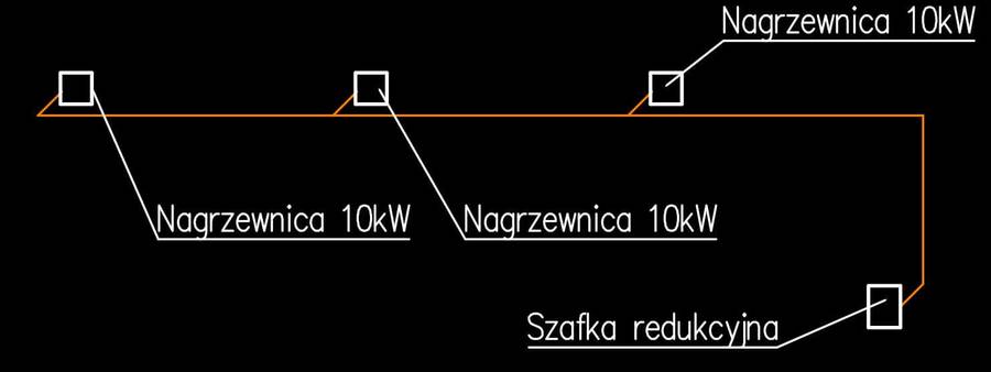
Our example installation in a small hall consists of 3 gas heaters, each with a power of 15kW. From the gas company, we usually have connection conditions, from which we read that the pressure after the reducer for our installation is 2.5kPa. From the technical data sheet of the heaters, we read that the maximum gas pressure for these devices is 5 kPa (50 mbar), and the minimum is 2kPa (20 mbar). Hence, we know that the pressure drop in the installation cannot exceed 0.5kPa (500 Pa), however, losses in the gas installation should not exceed 150-200Pa.

Gas Installation Diameter Selection
The gas installation from the reducer to the first distribution should deliver a total of 45 kW, after the first distribution 30 kW, and the last section to the consumer is 15 kW. The lengths of the sections are shown in the previous drawing. Let's look at the calculator and enter the appropriate values. For individual sections, the program selected the following pipe diameters:
- 15kW - DN15 - 4.95 Pa/m
- 30kW - DN20 - 5.41 Pa/m (larger diameter chosen)
- 45kW - DN25 - 3.41 Pa/m (larger diameter chosen)
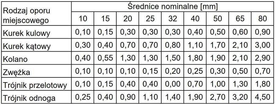
Let's assume that each horizontal section of the installation is 10m, and the risers are 4m. Hence, the total linear pressure loss will be: dP = 4.95 x 10 + 5.41 x 10 + 3.41 x 14 = 151.3 Pa Having selected the dimensions and calculated the linear pressure loss per running meter of the pipe, we should also take into account local pressure losses. We can do this by adding additional equivalent length of pipes due to local losses, using the table below. For our example, however, we will assume for simplicity that local losses will amount to 20% of linear losses. Taking into account linear resistances of 151.3 Pa and local ones of 0.2 x 151.3 = 30.3 Pa, and subtracting the increase in gas pressure in the four-meter vertical section 4 x 5.4 = 21.6 Pa. We obtain a total pressure drop of 151.3 + 30.3 - 21.6 = 160 Pa The selected pipe diameters meet the assumptions, i.e., the total pressure drop on the most unfavorable section is less than 200 Pa.
 Table 1 Equivalent Lengths
Summary
Diameter selection using the calculator in gas installations is very simple. If we know the minimum pressure required by the consumer and the available pressure at the reducer outlet, it is enough to enter the appropriate flow in the given sections and read the pressure drop. The flow velocity on the most loaded section should not exceed 6 m/s (K. Bąkowski, "Sieci i instalacje gazowe").
Back to articles list