
Compressed air installation — design, calculations, and pipe sizing
7 kwietnia 2026 | Installations
Compressed air is one of the most commonly used energy carriers in industry — it is used to power pneumatic tools, control automation systems, spray painting, and cleaning components. Unfortunately, it is also one of the most expensive utilities: it is estimated that only 10–15% of the electrical energy consumed by a compressor is converted into useful compressed air work, while the rest is lost as heat. This is precisely why proper design of the piping system is so important — every unnecessary pressure drop means higher electricity bills.
If you want to quickly check the pressure drop and select pipe diameters for your installation, use our compressed air calculator.
Why is the layout of a compressed air installation so important?
A compressor produces air at a specific pressure — most commonly 6–10 bar. However, before the medium reaches the point of use, it must overcome resistance in pipes, elbows, tees, valves, and filters. If the installation is poorly designed, the pressure at the tool nozzle can be 1–2 bar lower than at the compressor outlet. This forces the user to increase the operating pressure, which raises energy consumption by approximately 7% per bar.
A well-designed compressed air piping system:
- minimizes pressure losses (the recommended pressure drop across the entire installation is a maximum of 0,1 bar, and ideally below 0,5 bar including all components),
- ensures stable pressure at all points of use,
- reduces condensate formation in the pipework,
- allows future expansion of the facility without the need to replace pipes.
Pipe materials for compressed air installations
The choice of pipe material affects the durability of the installation, flow resistance, ease of installation, and operating costs. Below is a comparison of the most commonly used materials.
| Material | Advantages | Disadvantages | Roughness k [mm] |
|---|---|---|---|
Aluminium | Lightweight, smooth internal surface, quick installation (press-fit systems), no corrosion | Higher material cost | 0,001–0,015 |
Black steel | Low material cost, readily available, mechanically strong | Corrodes internally (rust contaminates the air), heavy, requires welding or threading | 0,05–0,10 |
Galvanised steel | Better corrosion resistance than black steel | Zinc layer flakes off over time and clogs filters, still heavy | 0,05–0,15 |
Copper | Very smooth surface, corrosion resistant, easy to solder | High cost, soft — easily damaged mechanically | 0,001–0,01 |
PE (polyethylene) | Inexpensive, lightweight, no corrosion, smooth internally | Limited operating pressure, UV sensitivity, not suitable for high temperatures | 0,007–0,02 |
Recommendation: In new industrial installations, aluminium systems with press-fit connectors are most commonly used. They offer the best compromise between low resistance, ease of installation, and durability. In small craft workshops, PE or copper pipes also work well.
Note on PVC: PVC pipes are strongly discouraged in compressed air installations. Under pressure, they can burst violently, creating dangerous shards. Many standards and health and safety regulations prohibit their use in pressurised installations.
Compressed air installation layouts
The choice of installation topology depends on the shape of the hall, the distribution of points of use, and pressure stability requirements.
Linear (through-flow) layout
The main pipe runs from the compressor in one direction, with branches leading to individual workstations. This is the simplest and cheapest layout, suitable for long, narrow halls with a small number of users.
The disadvantage of the linear layout is that the further from the compressor, the lower the pressure at the endpoint. Additionally, the entire flow passes through a single pipe, which generates larger pressure drops under heavy loads.
Ring (loop) layout
The main pipe forms a closed loop around the hall. Compressed air can reach each point of use via two paths, which equalises the pressure and reduces drops. This is the recommended layout for most industrial installations.
An additional advantage of the loop is that the effective diameter at each section is larger — the air splits into two streams, so the velocity in the pipe is lower, and consequently the resistance is lower.
Mixed layout
In practice, a combination of both layouts is often used: a ring as the main header with linear branches delivering air to workstations. In addition, there are manifolds that allow multiple tools to be connected at a single point.
Important rule: Main pipes should have a 1–2% slope in the direction of condensate drainage, with drain traps at the lowest points of the installation.
Calculating pressure drop in the installation
A key element of design is calculating the pressure drop in the pipeline to ensure that the pressure at the most distant point of use is sufficient. The pressure drop in a straight pipe is described by the Darcy-Weisbach equation:
Where:
- — pressure drop [Pa]
- — friction factor (dimensionless, depends on the Reynolds number and pipe roughness)
- — pipe section length [m]
- — internal pipe diameter [m]
- — compressed air density [kg/m³]
- — air flow velocity [m/s]
The density of compressed air depends on the operating pressure. For pressure [bar] at temperature [K]:
Where is the gas constant for air. For a pressure of 7 bar and a temperature of 20°C ( = 293 K), the density is approximately 8,32 kg/m³.
In engineering practice, a simplified empirical formula is more commonly used, which directly gives the pressure drop in bar:
Where:
- — pipe length [m]
- — air flow rate at standard conditions [l/s]
- — internal pipe diameter [mm]
- — operating pressure [bar]
The value 450 is an empirical constant that accounts for air properties and the friction factor for typical industrial pipes. For quick calculations, I encourage you to use the compressed air calculator, which automatically accounts for all the above relationships.
Recommended velocities and pipe diameters
Too high an air velocity in the pipe causes excessive pressure drops and noise. Too low a velocity means oversizing and unnecessary costs. The following recommended velocities are adopted:
- Main pipe (header): 6–8 m/s
- Branches: 8–10 m/s
- Tool connections: up to 15 m/s
The table below shows approximate pipe diameters depending on the air flow rate (at an operating pressure of 7 bar and a recommended main pipe velocity of 6–8 m/s):
| Flow rate [Nm³/min] | Flow rate [l/s at 7 bar] | Internal diameter [mm] | Typical aluminium pipe |
|---|---|---|---|
| 0,5 | 10,4 | 15–20 | DN 20 |
| 1,0 | 20,8 | 20–25 | DN 25 |
| 2,0 | 41,7 | 32–40 | DN 40 |
| 4,0 | 83,3 | 50–63 | DN 63 |
| 8,0 | 166,7 | 63–80 | DN 80 |
| 15,0 | 312,5 | 80–100 | DN 100 |
Pressure drop for different pipe materials
The pipe material affects the pressure drop due to the roughness of the internal surface. The table below compares the approximate pressure drop per 100 m of straight pipe with an internal diameter of 40 mm, at a flow rate of 1,5 Nm³/min and a pressure of 7 bar:
| Pipe material | Pressure drop per 100 m [bar] | Relative comparison |
|---|---|---|
| Aluminium (new) | 0,035 | 1,0× |
| Copper | 0,033 | 0,9× |
| PE | 0,038 | 1,1× |
| Black steel (new) | 0,065 | 1,9× |
| Black steel (after 10 years) | 0,12–0,20 | 3,4–5,7× |
As you can see, the difference between aluminium and old, corroded steel is enormous — the pressure drop can be up to 5–6 times greater. This is one of the main reasons why old steel installations are replaced with aluminium ones during plant modernisations.
Condensate management and air quality
Compressing air causes water vapour to concentrate. A compressor with a capacity of 5 Nm³/min, operating at 60% relative humidity and an ambient temperature of 25°C, produces approximately 10–15 litres of condensate per day. If this water is not removed, it leads to:
- corrosion of the internal pipe walls (especially steel pipes),
- damage to pneumatic tools and actuators,
- deterioration of quality in painting, sandblasting, and packaging processes,
- freezing in pipework running through unheated spaces.
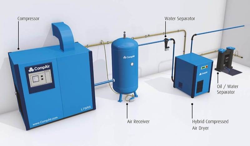
Air treatment system components
A properly designed installation should include the following components (in order from the compressor):
- Aftercooler — lowers the air temperature after the compressor, causing most of the water vapour to condense. Usually built into the compressor.
- Cyclone separator — removes coarse water and oil droplets immediately after the cooler.
- Pressure receiver (tank) — buffers pressure, smooths pulsations, and allows further condensate settling.
- Dryer — depending on requirements, a refrigerant dryer (dew point +3°C) or an adsorption dryer (dew point down to –40°C and below) is used.
- Fine filter — removes solid particles and residual oil (coalescing filters down to 0,01 mg/m³).
- Automatic drain traps — installed at the lowest points of the installation, at the ends of dead-end sections, and below every vertical drop.
Compressed air quality classes according to ISO 8573-1
The ISO 8573-1 standard defines compressed air purity classes in terms of solid particle content, water, and oil. For typical workshop applications, class 4:4:4 is sufficient, while for the food or pharmaceutical industry, class 1:2:1 or higher is required.
Practical example: installation for a small workshop
Let us assume we are designing a compressed air installation for a mechanical workshop measuring 15 × 10 m. The following tools operate simultaneously in the workshop:
- 2 pneumatic impact wrenches (consumption of 400 Nl/min each),
- 1 spray gun (250 Nl/min),
- 1 blow gun (150 Nl/min).
Step 1: Calculating the air demand
We sum up the demand: 400 + 400 + 250 + 150 = 1 200 Nl/min = 1,2 Nm³/min.
We apply a simultaneity factor (not all tools operate at the same time) — we assume 0,75:
We add a 10–15% reserve for leaks and future expansion:
Step 2: Compressor selection
We select a screw compressor with a capacity of at least 1,04 Nm³/min (approx. 62 Nm³/h) at a pressure of 8 bar. In practice, a compressor with a power rating of approximately 7,5 kW is chosen.
Step 3: Main pipe diameter selection
We adopt a ring (loop) layout due to the rectangular shape of the hall. Loop perimeter: 2 × (15 + 10) = 50 m. In a ring layout, the air splits into two streams, so the flow in each half is approximately 0,52 Nm³/min.
Using the table above or the compressed air calculator, for a flow rate of 0,52 Nm³/min at 8 bar, we select an aluminium pipe DN 25 (internal diameter approx. 22 mm).
Step 4: Checking the pressure drop
Based on the pressure drop table above, for an aluminium pipe DN 25 (internal diameter approx. 22 mm) and a flow rate of 0,52 Nm³/min at 8 bar, the unit pressure drop is approximately 0,035 bar per 100 m. For half of the ring ( = 25 m):
The pressure drop is only 0,009 bar, which is an excellent value. Even after adding local resistances (elbows, tees — a factor of 1,5–2,0 times the straight-line length is assumed), we remain well below the permissible limit of 0,1 bar. You can perform exact calculations for your installation using the compressed air calculator.
Step 5: Branch selection
Connections to workstations are made with DN 15 pipes (internal diameter approx. 13 mm), which are sufficient for individual tools with a flow rate of up to 500 Nl/min. The branch lengths in our workshop are a maximum of 5 m, so the pressure drop across them will be negligible.
Most common mistakes in compressed air installations
To conclude, it is worth listing the most common mistakes that lead to operational problems:
- Pipe diameters too small — generate excessive pressure drops and force the compressor to operate at higher pressure.
- No drain traps — condensate accumulates at the lowest points and damages tools.
- Sharp angles and abrupt direction changes — every 90° elbow generates resistance equivalent to several metres of straight pipe. Where possible, use large-radius bends.
- No buffer tank — causes large pressure fluctuations, especially when using tools with high instantaneous demand.
- Using PVC pipes — dangerous due to the risk of sudden bursting under pressure.
- No reserve for expansion — it is worth selecting pipe diameters one size larger than the minimum required.
Summary
Designing a compressed air installation requires taking many factors into account: from selecting the pipe material, through calculating the pressure drop, to managing condensate. The key principles are: choosing a ring layout for better pressure distribution, using modern materials (aluminium) instead of steel, ensuring an adequate air treatment system, and regularly checking for leaks.
For quick pipe diameter selection and pressure drop verification in your installation, use our compressed air calculator — simply enter the flow rate, pressure, and pipeline length, and the calculator will determine the optimal diameter and pressure drop.
Back to articles list