
How to calculate underfloor heating step by step — a guide with calculator
29 marca 2026 | Heating
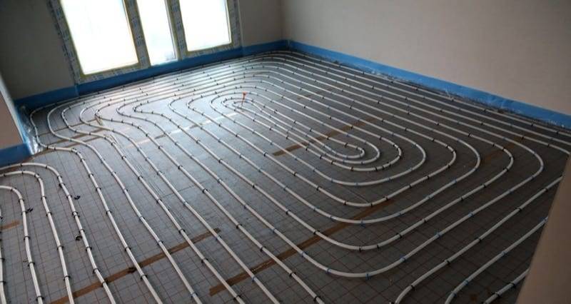
Underfloor heating is one of the most popular heating systems in new construction. However, correctly calculating the installation requires considering many factors — from room heat losses, through the type of floor covering, to the heat source parameters. Errors in calculations lead to underheated rooms, cracking tiles or unnecessarily high energy bills.
If you want to quickly calculate underfloor heating without manual calculations, use our underfloor heating calculator. The calculator automatically selects pipe spacing, calculates loop length and checks whether underfloor heating will cover the heat losses.
Input data for calculations
Before you start calculating underfloor heating, you need to gather several key pieces of information:
-
Room heat losses — calculated according to the PN-EN 12831 standard. This is the primary input that determines the required heating output of the floor. Heat losses depend on the building insulation, window size, climate zone and ventilation.
-
Supply and return temperature parameters — depend on the heat source (heat pump, condensing boiler, solid fuel boiler). For underfloor heating, the supply temperature is significantly lower than for radiators.
-
Type of floor covering — porcelain tiles, laminate panels, hardwood flooring or carpet. Each material has a different thermal resistance that affects heating efficiency.
-
Heated area — not the entire room area is actively heated. From the total area we subtract areas under permanent furniture (built-in wardrobes, bathtub) and areas near walls (border zone).
-
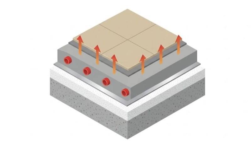
Screed thickness and type — standard cement screed (minimum 65 mm above the pipe) or anhydrite screed (minimum 45 mm above the pipe). Anhydrite has better thermal conductivity (–) than concrete (–), which allows for a lower supply temperature.
Supply and return temperature
Underfloor heating operates at significantly lower temperatures than radiators. The maximum supply temperature should not exceed 55°C — higher values risk damaging the screed and PEX pipes.
In practice, the supply temperature depends on the heat source:
| Heat source | Supply [°C] | Return [°C] | Notes |
|---|---|---|---|
Heat pump | 30–35 | 25–30 | Optimal for COP |
Condensing boiler | 40–45 | 30–35 | Flue gas condensation at low return |
Solid fuel boiler | 45–55 | 35–45 | Requires a mixing valve |
The temperature difference between supply and return () is typically 5–10°C. The smaller the difference, the more uniform the floor temperature distribution, but at the same time a greater flow of the heating medium is required.
With heat pumps, it is worth aiming for the lowest possible supply temperature — each degree less means a 2–3% increase in COP (heat pump efficiency).
Maximum floor surface temperature
The PN-EN 1264 standard specifies maximum permissible floor surface temperatures for user comfort and health:
| Zone | Max. temperature [°C] | Description |
|---|---|---|
Occupied zone | 29 | Living rooms, bedrooms, kitchens |
Border zone | 35 | 1 m strip along external walls |
Bathroom | 33 | Underfloor heating in bathrooms |
A temperature of 29°C in the occupied zone corresponds to a maximum heat flux density of approximately 100 W/m² (with standard floor construction). Exceeding this temperature causes discomfort — "hot feet" and circulation problems during prolonged exposure.
The border zone is a strip up to 1 m wide along external walls with windows. A higher temperature (35°C) is permitted here because nobody stays in this zone for extended periods. This allows for a smaller pipe spacing under windows and compensates for increased heat losses.
PEX pipe spacing — how many metres of pipe per m2
Pipe spacing is the distance between the axes of adjacent pipes in an underfloor heating loop. Standard spacings are 10, 15, 20, 25 and 30 cm. The smaller the spacing, the greater the heating output of the floor — but also more pipe and higher cost.
| Pipe spacing [cm] | Metres of pipe per m2 | Application |
|---|---|---|
10 | 10,0 | Border zone, bathrooms — max heating output |
15 | 6,7 | Rooms with high heat losses |
20 | 5,0 | Standard spacing — most rooms |
25 | 4,0 | Well-insulated rooms |
30 | 3,3 | Minimum requirements — passive houses |
The number of metres of pipe per m2 is calculated using the formula:
where — pipe spacing expressed in metres (e.g. 0,15 m for 15 cm spacing).
The total pipe length in a loop is:
where:
— heated area [m²]
— pipe spacing [m]
— distance from the manifold to the room [m]
Maximum loop length
An excessively long loop causes excessive pressure drop and uneven temperature distribution. Maximum recommended loop lengths:
| Pipe diameter | Max. loop length [m] |
|---|---|
PEX 16×2,0 mm | 100–120 |
PEX 17×2,0 mm | 100–120 |
PEX 20×2,0 mm | 120–150 |
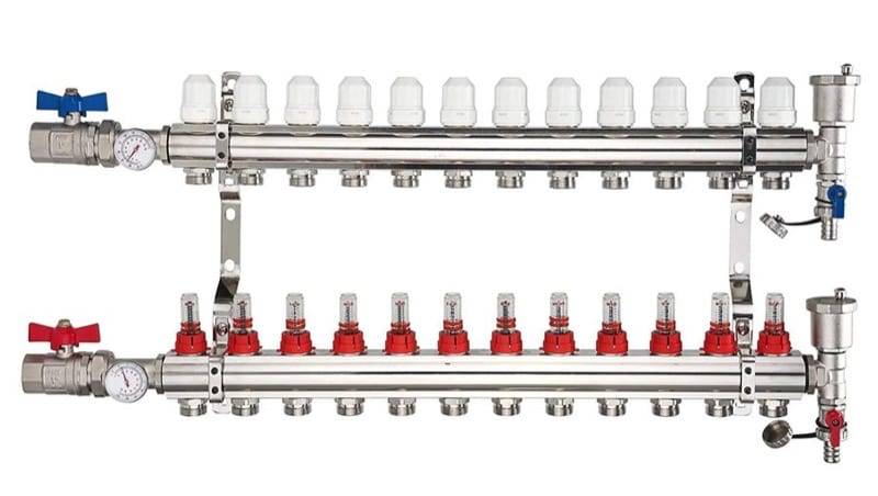
The values given include the total pipe length — including the connection sections from the manifold to the room. If the calculated pipe length exceeds the maximum for a given diameter, the room should be divided into two or more loops. It is important that all loops in a single installation have similar lengths — the difference should not exceed 10–15%, which facilitates hydraulic balancing at the manifold.
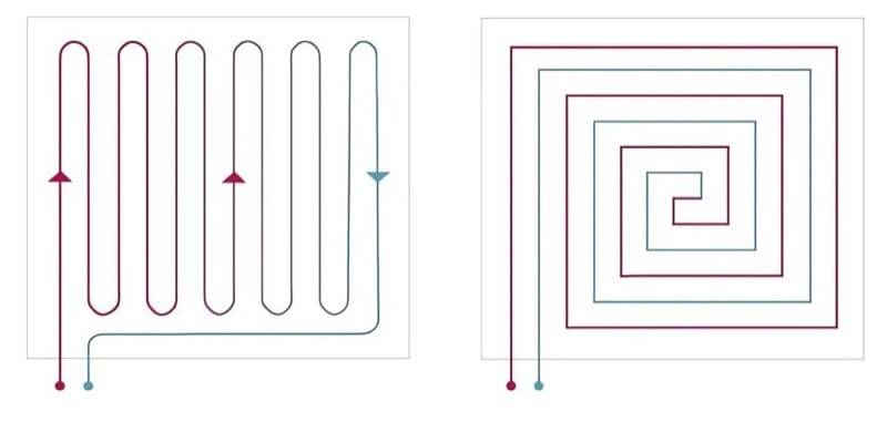
Loop laying patterns — spiral vs serpentine
The way pipes are laid in the floor affects the uniformity of temperature distribution:
Spiral — supply and return pipes run alternately next to each other. This means a hot supply pipe is adjacent to a cooler return pipe, resulting in a very uniform temperature distribution across the entire surface. This solution is recommended in most cases, especially with heat pumps with low supply temperatures.
Serpentine (meander) — the pipe runs in one direction, turns around and returns in parallel sections. At the entry point to the room the floor is warmest, and at the exit point it is coolest. Serpentine layout is mainly used in border zones (tighter spacing under windows) or in small rooms such as bathrooms.
Double spiral — a variant of the spiral used in large rooms. Two spirals share a single loop, which allows covering a larger area while maintaining the permissible loop length.
In practice, the most common approach is a spiral layout in the occupied zone (15–20 cm spacing) with a serpentine border zone under windows (10–15 cm spacing).
Thermal resistance of floor coverings
The type of floor covering has a significant impact on underfloor heating efficiency. Each material represents additional thermal resistance between the screed and the room — the higher the resistance, the less heat reaches the floor surface.
| Floor covering | Thermal resistance [m²·K/W] | Impact on underfloor heating |
|---|---|---|
Porcelain / ceramic tiles | 0,01–0,02 | Ideal — minimal losses |
Laminate panels | 0,05–0,10 | Good — requires underfloor heating underlay |
Hardwood flooring (15 mm) | 0,10–0,15 | Acceptable — lower efficiency |
Carpet | 0,15–0,25 | Not recommended — significant output loss |
The PN-EN 1264 standard recommends that the total thermal resistance of layers above the pipes (covering + adhesive + underlay) should not exceed 0,15 m²·K/W. Above this value, underfloor heating efficiency drops drastically — it may be necessary to reduce pipe spacing or increase the supply temperature.
In practice, this means that porcelain and ceramic tiles are the best covering for underfloor heating. Laminate panels work well, provided that thin underlays designed for underfloor heating are used (not standard polystyrene underlays). Hardwood flooring is acceptable but requires stable species (oak, ash) with a thickness of up to 15 mm. Carpet is strongly not recommended.
Heat flux density — will underfloor heating cover the losses?
The key question when designing underfloor heating: does the floor emit enough heat to cover the room's heat losses?
The required heat flux density is calculated using the formula:
where:
— room heat losses [W]
— heated (active) area [m²]
The maximum heat flux density that underfloor heating can deliver depends on the supply temperature, pipe spacing, floor construction and thermal resistance of the covering. According to the PN-EN 1264 standard, the approximate limiting value is determined from the relationship:
where:
— floor heat transfer coefficient, assumed for a heating floor
— maximum floor surface temperature [°C] (29°C in the occupied zone)
— room temperature [°C]
For a living room (, ):
This means that in the occupied zone, underfloor heating can deliver a maximum of approximately 100 W/m². If the required heat flux density exceeds this value, underfloor heating alone will not cover the heat losses and it is necessary to:
- use a border zone with smaller spacing (up to 35°C → approx. 162 W/m²),
- add supplementary radiators or fan coil units,
- improve building insulation (reduce heat losses).
Practical example — step-by-step calculation
Let us calculate underfloor heating for a living room with the following parameters:
- Room area: 25,0 m²
- Heated (active) area: 22,0 m² (deducting permanent furniture)
- Heat losses: Q = 1 500 W
- Heat source: heat pump, supply 35°C / return 30°C
- Floor covering: ceramic tiles ()
- Room temperature: 20°C
- Pipes: PEX 16×2,0 mm
- Distance from manifold: 5 m
Step 1: Required heat flux density
The value 68,2 W/m² is less than the limiting 100 W/m² — underfloor heating will cover the heat losses.
Step 2: Selecting pipe spacing
With a supply temperature of 35°C, return of 30°C, room temperature of 20°C and ceramic tiles on the floor, to achieve a heat flux density of ~68 W/m² a spacing of 15 cm is needed.
With 20 cm spacing the heat flux density would be too low (~55 W/m²), and with 10 cm (~85 W/m²) we would unnecessarily use more pipe.
Step 3: Calculating pipe length
The length of 156,7 m exceeds the maximum for PEX 16×2,0 mm pipe (100–120 m). It is necessary to divide into 2 loops:
- Loop 1: 11,0 m² →
- Loop 2: 11,0 m² →
Both loops have identical lengths — an ideal situation for hydraulic balancing.
Step 4: Checking floor surface temperature
Average heating medium temperature:
With a heat flux density of 68,2 W/m² and a heat transfer coefficient of 10,8 W/(m²·K):
The surface temperature of 26,3°C is below the 29°C limit — the comfort condition is met.
Example summary
| Parameter | Value |
|---|---|
Heat flux density | 68,2 W/m² |
Pipe spacing | 15 cm |
Number of loops | 2 |
Single loop length | 83,3 m |
Total pipe length | 166,6 m |
Floor surface temperature | 26,3°C |
Result | Underfloor heating will cover the heat losses |
All these calculations are performed automatically by our underfloor heating calculator — simply enter the room data and the calculator will select the pipe spacing, calculate the loop length and check the comfort conditions.
Most common mistakes when designing underfloor heating
-
Pipe spacing too wide — assuming 30 cm spacing "because everyone does it that way". With heat pumps with low supply temperatures (30–35°C), 30 cm spacing provides insufficient heating output. The standard for heat pumps is 15 cm in the occupied zone.
-
Ignoring the thermal resistance of the floor covering — designing for ceramic tiles and then laying laminate panels or hardwood. Changing the covering from tiles () to wood () can reduce the floor's heating output by as much as 15–20%.
-
Supply temperature too high — setting the supply to 50–55°C "just to be safe". This leads to floor overheating above 29°C, thermal discomfort and cracking of tiles or hardwood.
-
No border zone — omitting tighter pipe spacing under windows. A border zone with 10 cm spacing compensates for increased heat losses at the external wall and prevents feeling cold near windows.
-
Loops too long — exceeding the maximum loop length. Result: uneven temperature distribution (beginning of the loop hot, end cold) and excessive pressure drop hindering the circulation pump operation.
-
Unequal loop lengths — one loop 50 m, another 120 m on the same manifold. Difficult to balance hydraulically — the heating medium "takes the shortcut" through the shorter loop.
-
Not accounting for permanent furniture — routing loops under built-in wardrobes and bathtubs. Lack of heat dissipation causes local overheating of the screed and pipes, which shortens the installation's lifespan.
-
Omitting expansion joints — for areas exceeding 40 m² or when the room side length exceeds 8 m, expansion joints in the screed are necessary. Lack of expansion joints leads to cracking of the screed and ceramic tiles due to thermal expansion. Pipes passing through expansion joints must be protected with a protective conduit.
Summary
Correctly calculating underfloor heating requires considering many factors: room heat losses, heat source parameters, type of floor covering and temperature limits from the PN-EN 1264 standard. The key stages are:
- calculating the required heat flux density (),
- selecting pipe spacing appropriate for the installation parameters,
- calculating the loop length and checking whether it exceeds the maximum,
- verifying the floor surface temperature (max 29°C in the occupied zone).
The entire process can be performed automatically using our underfloor heating calculator. The calculator takes into account all the above parameters and delivers results in seconds — without manual calculations and risk of error.
Back to articles list