
Structural Design of Buried Pipes per ATV-A 127 — Designer's Guide
8 kwietnia 2026 | Pipes
Designing buried pipes — sewer, water and industrial — requires a structural check, independent of hydraulic calculations. A pipe placed in a trench works together with the surrounding soil: loads from soil, road traffic and groundwater are transferred to the pipe, which resists them through its own stiffness and the reaction of the surrounding ground. Neglecting these checks is the most common cause of pipe deformation and cracking after years of service.
In this guide we step by step discuss the structural calculation methodology for buried pipes used by our Buried Pipe Load Calculator. The calculator combines two recognised sources: the classic Modified Iowa Formula (Watkins & Spangler 1958) for deflection and buckling formulas, and ATV-DVWK-A 127 for pipe-soil system classification (VRB coefficient), soil modulus tables, traffic load models (SLW 30/60, UIC 71) and Marston's silo theory for earth load in a trench. The article is intended for sanitary designers, water and sewer engineers and buried network structural designers.
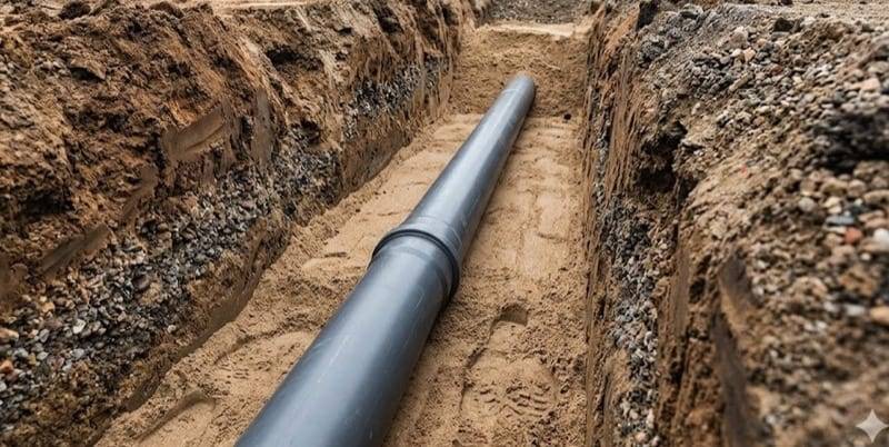
Rigid and flexible pipes — VRB classification
The first step in the structural design of buried pipes is to distinguish whether we are dealing with a flexible pipe (PVC-U, HDPE, PP, GRP) or a rigid one (concrete, vitrified clay, ductile iron, steel). This distinction is crucial because each group requires a different verification methodology and accounts for a different pipe-soil interaction mechanism.
The classification uses the VRB coefficient (German Verformungs-Reaktions-Beiwert), which compares the pipe's ring stiffness with the stiffness of the surrounding soil:
Where:
- — nominal pipe stiffness SN per EN ISO 9969 ,
- — horizontal subgrade reaction modulus .
The factor 8 in the numerator comes from converting nominal stiffness SN () to ring stiffness , because the mean radius . Both values are used interchangeably in pipeline literature — in our calculator is the base value and the factor 8 appears explicitly in every formula that requires ring stiffness.
| VRB | System type | Typical materials |
|---|---|---|
| < 0.1 | highly flexible | HDPE, PP SN 4 |
| < 1 | flexible | PVC-U SN 8, PP SN 8 |
| 1–100 | semi-flexible | GRP (glass-fibre reinforced polyester) |
| > 100 | rigid | concrete, vitrified clay, ductile iron, steel |
In a flexible system the pipe deflects slightly vertically under load and at the same time expands sideways, mobilising the reaction of the surrounding soil. The soil "helps" the pipe — it takes part of the load through horizontal lateral earth pressure. For a typical PVC-U SN 8 pipe in a properly executed bedding, about 80% of the system bearing capacity comes from lateral soil support and only about 20% from the stiffness of the pipe itself. Therefore the main checks for flexible pipes are deflection, ring stresses and wall buckling stability.
In a rigid system the pipe practically does not deflect — it must carry the full vertical load by itself. The parameters of the lateral soil (zone E₂) are secondary in this case. The calculation method is completely different: instead of a deflection check, a crushing strength check is performed against the pipe class (catalogue value from the manufacturer, classes per EN 1916 for concrete and EN 295 for vitrified clay) and a bedding factor depending on the bedding class.
Loads acting on a buried pipe
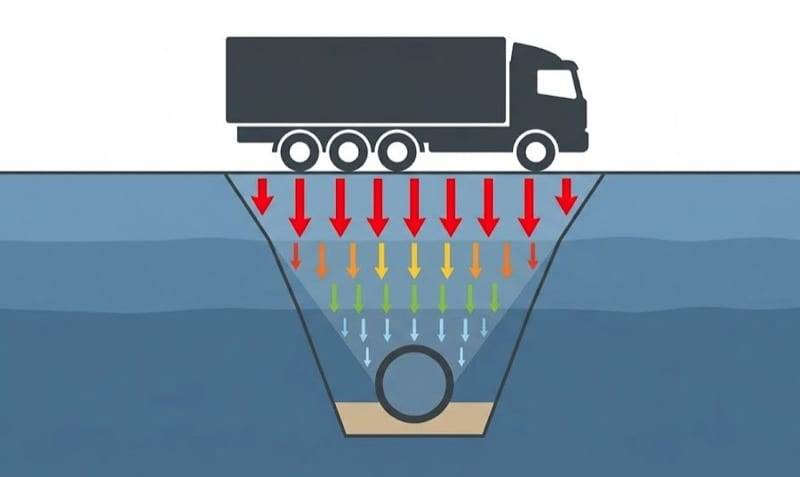
A buried pipe is subject to four main types of loads which must be considered together: earth load, traffic surface load, hydrostatic load from groundwater and — in pressure pipes — the internal pressure of the fluid.
Earth load — Marston's silo theory
For placement in an embankment (pipe under a soil embankment, open space) the earth load is calculated as the full weight of the soil column above the pipe crown:
For placement in a narrow trench Marston's silo reduction is applied:
Where:
- — soil unit weight , typically 18–20 kN/m³ (in the calculator entered by the user, default 18 kN/m³),
- — cover depth to the pipe crown ,
- — silo reduction coefficient .
The silo effect means that the narrower the trench, the greater the proportion of the soil weight that "hangs" on the trench walls through friction — less load reaches the pipe. The coefficient depends on the trench slenderness , the native soil group and the type of trench wall support (sheeting). Trench width and sheeting type are discussed in detail in the "Pipe bedding and installation" section.
Road traffic load
The static load from surface traffic is multiplied by a dynamic factor which accounts for vehicle impact and vibration effects:
The calculator supports the following traffic load classes:
| Class | Standard source | Application |
|---|---|---|
| PEDESTRIAN | ATV-A 127 | pedestrian traffic, vehicle-free zones |
| LKW 12 | DIN 1072 | 12 t vehicle, access roads |
| SLW 30 | DIN 1072 | 30 t vehicle, local roads |
| SLW 60 | DIN 1072 | 60 t vehicle, national and regional roads |
| UIC 71 | EN 1991-2 | railway loads |
DIN 1072 has formally been withdrawn, however SLW 30/60 classes are still in use in Polish design practice and are applied in the ATV-A 127 guidelines. For new road infrastructure designed according to Eurocode, the LM1 model per EN 1991-2 (axle load 300 kN) is used as an alternative — this model is not currently supported by the calculator.
Static values for class SLW 60 (per ATV-A 127 Table 4):
| Depth H [m] | pv,stat [kN/m²] |
|---|---|
| 0.5 | 143 |
| 1.0 | 60 |
| 1.5 | 33 |
| 2.0 | 21 |
| 3.0 | 10 |
| 5.0 | 4 |
The dynamic factor decreases with depth — at shallow cover the vehicle impact effect dominates, at large depth the load becomes practically static:
| Depth H [m] | Factor φ |
|---|---|
| 0.5 | 1.50 |
| 1.0 | 1.40 |
| 1.5 | 1.25 |
| 2.0 | 1.15 |
| 3.0 | 1.10 |
| ≥ 4.0 | 1.00 |
Hydrostatic load from groundwater
If the groundwater table is above the pipe crown, the pipe is additionally subject to a hydrostatic load:
Where:
- kN/m³ — water unit weight,
- — cover depth to the pipe crown ,
- — groundwater table depth from the ground surface .
If the water table is below the pipe crown (), hydrostatic load is not considered.
Internal pressure (pressure pipes)
For pressure pipes — water mains, pressurised sewers — the hoop stresses induced by the internal fluid pressure must also be considered. They are calculated using Barlow's formula:
Where:
- — working pressure inside the pipe ,
- — mean pipe diameter ,
- — wall thickness .
This check is not performed for gravity sewer pipes, where flow takes place at atmospheric pressure on the liquid surface. For pressure pipes, hoop stress is added to the stresses from external loads, giving a resultant stress to be compared with the allowable material value.
Pipe-soil system stiffness
A key concept in the structural design of buried pipes is the pipe-soil system stiffness — the stiffness of the pipe itself (a material-geometric parameter) and the stiffness of the surrounding soil (a parameter depending on the zone around the pipe and its compaction) are described separately. The interaction between these two stiffnesses determines how the whole system will react to load.
Ring stiffness of the pipe S₀
The ring stiffness of a pipe is its resistance to deflection under external load. In the EN ISO 9969 convention (laboratory measurement) it is calculated as:
Where:
- — pipe wall thickness ,
- — modulus of elasticity of the pipe material ,
- — mean pipe diameter .
The EN ISO 9969 standard defines nominal stiffness classes SN as a measurement value (laboratory ring compression test): SN 2, SN 4, SN 8, SN 16 — the number denotes stiffness in . In the catalogues of PVC-U, HDPE, PP and GRP pipe manufacturers the SN class is the basic selection parameter.
However, the Modified Iowa formulas for deflection and buckling use the ring stiffness , where is the mean pipe radius. Since , the following relation holds:
The factor 8 appears explicitly in all calculator formulas where ring stiffness is needed. Omitting this factor is one of the most common mistakes in implementing ATV/Spangler formulas — it results in an overestimation of deflection of the order of 50% (for typical pipe-soil configurations).
Short-term and long-term modulus — plastic creep
The modulus of elasticity of thermoplastics (PVC, PE, PP) is not constant — it decreases with time due to creep. ATV-A 127 and good design practice require the pipe statics to be checked in two states: short-term (, state immediately after installation) and long-term (, state projected for 50 years of service).
| Material | E24h [MPa] | E50y [MPa] | Drop |
|---|---|---|---|
| PVC-U | 3,000 | 1,200 | ~60 % |
| HDPE | 1,100 | 300 | ~73 % |
| PP | 1,500 | 500 | ~67 % |
| GRP | 10,000 | 7,000 | ~30 % |
Practical conclusion: the SN class given in the manufacturer's catalogue is the nominal value determined from a short-term test. The actual stiffness of the pipe after 50 years of operation may be significantly lower — therefore deflection and buckling checks should always be performed for both moduli ( and ). Rigid pipes (concrete, vitrified clay, ductile iron, steel) are not subject to creep — for them .
Subgrade reaction modulus S_Bh vs. soil modulus E₂
These two concepts are often confused, and the difference is fundamental:
- — soil deformation modulus, a material parameter depending on the soil group and degree of compaction. Read from standard tables.
- — horizontal subgrade reaction modulus, a pipe-soil system parameter. In the calculator, for typical conditions is assumed, but in the full ATV-A 127 form, additional reduction coefficients depending on trench width and zones E1–E4 around the pipe are included.
alone is not sufficient to fully describe pipe-soil interaction — the full trench geometry and the stiffness distribution in zones E1–E4 must be known.
| Group | Description | E2 [MN/m²] @ 95 % DPr | Feasibility 97 % DPr |
|---|---|---|---|
| G1 | gravel, sandy gravel | 9–16 | achievable |
| G2 | medium and coarse sand | 6–10 | achievable with care |
| G3 | fine sand, silt | 3–5 | difficult, requires mechanical compaction |
| G4 | clay, loam, peat | 1–2 | practically unachievable |
Warning for designers: assuming in the design for G4 soils (clays, loams) is one of the most common design mistakes. In cohesive soils such a level of compaction is practically impossible to achieve with standard construction methods. The result is a "paper" design much safer than the actual structure — after years the pipe deflection exceeds the allowable values, even though the design showed a large reserve.
Soil zones E1–E4
ATV-A 127 divides the soil around the pipe into four zones with different roles in transferring loads (terminology from the German standard, used in Polish design practice):
- E1 — fill zone above the pipe (German Überschüttung) — from the pipe crown to ground level; transfers vertical soil load onto the pipe,
- E2 — lateral zone of the bedding (German Einbettung, pipe zone) — to the sides of the pipe; most important for flexible pipes — directly supports the pipe and transfers the horizontal reaction,
- E3 — native soil of the trench walls (German anstehender Boden) — its stiffness affects the silo effect and the load distribution in the surrounding soil,
- E4 — soil beneath the bottom of the trench (beneath the levelling bedding) — the base of the whole system.
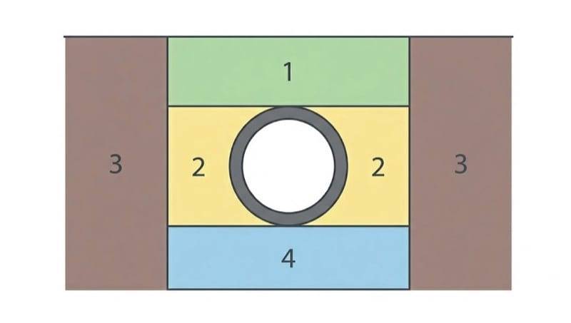
Each zone may have a different soil type and a different degree of compaction. The calculator computes the resultant subgrade reaction modulus taking all four zones into account. A simplified mode (one soil around the pipe — suitable for typical estate-network installations) and an advanced mode (separate definition of each zone — for projects in varied soil conditions or where the native soil differs from the designed bedding) are available.
System classification — synthesis
Knowing the pipe stiffness and the subgrade reaction modulus , the calculator computes the VRB coefficient (formula from the second section) and classifies the system as flexible, semi-flexible or rigid. This classification determines which checks will be performed — flexible pipes are checked for deflection, ring stresses and buckling stability, rigid pipes for crushing strength.
Pipe installation and bedding
The way a pipe is installed in the trench — the type of excavation, the bedding class, the support angle — has a direct influence on the design load and the stress distribution in the pipe. Two pipes with identical parameters can behave completely differently depending on the quality of subgrade preparation and lateral bedding.
Installation types and trench support
The calculator considers two basic pipe installation types:
- Narrow trench — pipe laid in an open excavation with vertical or slightly sloped walls; used in most buried networks. Silo effect (reduction ) fully active.
- Embankment — pipe laid in the bedding with a full soil column above the crown (road embankment, dam, or a pipe placed on native ground and covered over). No silo effect — the vertical load is transferred without reduction ().
Trench walls can be supported in different ways: continuous sheeting (steel panels), braced sheeting (cross struts), sheet piling (piles driven into the ground). Each of these methods changes the wall friction coefficient, and with it the value of the silo coefficient .
Design note: ATV-A 127 requires a separate verification for the temporary state (sheeting installed, pipe during construction) and the final state (sheeting removed, trench backfilled). After sheeting removal the friction on the trench walls disappears, the pipe load increases — for some configurations it is the final state that is critical.
Bedding classes A / B / C / D and support angle α
The calculator uses a simplified four-level bedding class scale (consistent with Polish design practice), which is internally mapped to the ATV-A 127 Table 7 standard classes:
| Class | Execution method | ATV equivalent |
|---|---|---|
| A | Concrete encasement — concrete in the bottom and side zone | A2 |
| B | Bedding compacted to pipe axis (design standard) | B2 |
| C | Loose bedding or manually compacted without control | C |
| D | Flat trench bottom, no bedding | C (conservative) |
The bedding class combined with the support angle (bedding geometry — 60°, 90°, 120° or 180°) determines the calculation coefficient (vertical load distribution in the pipe) and the coefficients and used in the ring stress check. The calculator applies the values of these coefficients per ATV-A 127 Table 7, after mapping the A/B/C/D classes to the standard A2/B2/C classes:
| Angle α | A (A2) | B (B2) | C | D (C) |
|---|---|---|---|---|
| 60° | 0.337 | 0.405 | 0.462 | 0.462 |
| 90° | 0.294 | 0.352 | 0.400 | 0.400 |
| 120° | 0.256 | 0.303 | 0.343 | 0.343 |
| 180° | 0.189 | 0.218 | 0.245 | 0.245 |
Interpretation: a support angle of 60° means a pipe resting on a narrow strip of subgrade (uneven bedding) — the reaction concentrates along the line of contact, stresses at the invert increase. 180° represents a full semi-circular support (e.g. in concrete encasement) — the reaction is distributed uniformly, stresses decrease. Class A (concrete encasement) gives the lowest coefficients, because the pipe works in conditions similar to laboratory. Classes C and D are uncontrolled bedding or no bedding — the calculator conservatively treats both cases as ATV-A 127 class C.
Trench width per EN 1610
Minimum trench widths follow from the working space necessary to lay the pipe and execute the bedding according to the design. The EN 1610 standard (Table 1) specifies the minimum as the outer diameter of the pipe plus a working margin depending on pipe size:
| Outer diameter OD [mm] | Minimum trench width |
|---|---|
| OD ≤ 225 | OD + 0.40 m |
| 225 < OD ≤ 350 | OD + 0.50 m |
| 350 < OD ≤ 700 | OD + 0.70 m |
| 700 < OD ≤ 1200 | OD + 0.85 m |
| OD > 1200 | 1.5 × OD (working space) |
Note: wider trenches reduce the silo effect — the soil does not "hang" on the walls, and the full weight of the soil column reaches the pipe. On the other hand, a trench that is too narrow makes it impossible to execute the required bedding class — the actual bedding class in such conditions drops to C or D. The designer must choose a compromise between these two effects, remembering that the EN 1610 minimum widths are a construction minimum, not a design one.
Concrete encasement — change of structural scheme
A flexible pipe (PVC-U, HDPE, PP) encased in concrete ceases to be an independent element — it becomes a composite pipe-concrete section with a stiffness much higher than the pipe alone. When activated by the "concrete encasement" checkbox, the calculator changes the calculation scheme and treats the system as a rigid pipe. This solution is used for crossings under highly loaded roads, railways, in zones of difficult soil conditions and in places where normal bedding parameters cannot be achieved (e.g. when the required compaction class cannot be executed).
Checks for flexible pipes
For flexible pipes (PVC-U, HDPE, PP, GRP) the calculator performs four basic limit state checks: vertical deflection, ring stresses in the wall, buckling stability and — with high groundwater — uplift of an empty pipe.
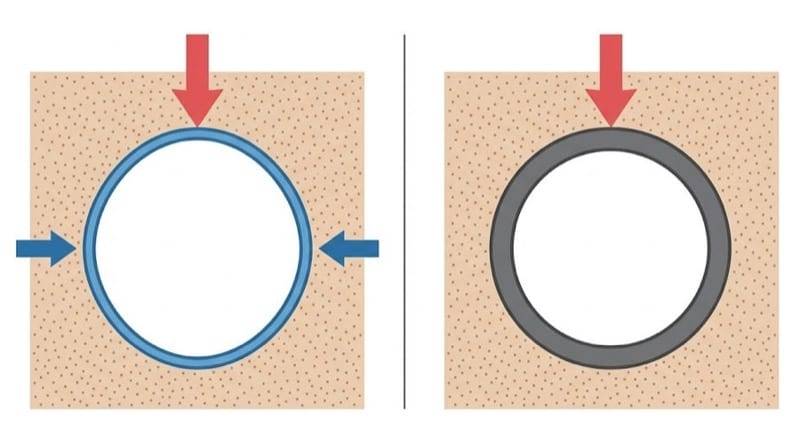
Vertical deflection and the 6 % criterion
Vertical deflection of the pipe crown under the total load is calculated using the Modified Iowa Formula (Watkins & Spangler 1958), which the calculator applies in the form:
Where:
- — vertical load coefficient (from ATV-A 127 Table 7, depending on bedding class and support angle),
- — earth load ,
- — traffic load ,
- — mean pipe radius ,
- — nominal pipe stiffness SN per EN ISO 9969 ,
- — horizontal subgrade reaction modulus (× 1000 → ).
Key note — factor 8 at : the stiffness from pipe manufacturer catalogues is the nominal stiffness per EN ISO 9969, defined as . In the classic Iowa formula, however, the ring stiffness is used, and since , then . Therefore the factor 8 is an inseparable part of the formula and omitting it leads to an overestimation of deflection of the order of 50 % (for typical pipe/soil stiffness ratios).
The result is expressed in millimetres. Percentage deflection is referred to the mean pipe diameter:
The 6 % criterion comes from EN 13476 (thermoplastic piping systems for non-pressure underground sewer networks) and is the most commonly applied limit in Polish design practice. This value serves two functions: limit deflection after 50 years (design) and a TV inspection limit at work acceptance (execution). Under DB AG railways the limit is stricter and equals 2 %.
Double check: good design practice requires deflection calculation in two states:
- initial state — with modulus (stiffness of a newly installed pipe),
- long-term state — with modulus (stiffness after 50 years of creep).
Both must fall within the 6 % limit. In HDPE pipes, where the modulus drops by ~73 %, the long-term state is always more critical. By default the calculator performs the deflection calculation for the long-term state (modulus ), which is a conservative approach. Some national guidelines (including ITB) apply a stricter 5 % limit as a safety margin — especially for collector networks with long-term service.
Ring stresses at three control points
The stress check consists of calculating the ring force and bending moment at three characteristic points of the pipe: crown (top), springline (sides) and invert (bottom):
Resultant stress in the pipe wall (extreme fibre):
Where:
- , — coefficients from ATV-A 127 Table 7 (depending on bedding class and support angle),
- — total load ,
- — wall thickness ,
- — cross-sectional area of the wall per unit length ,
- — bending resistance modulus .
Criterion: at each of the three control points.
In flexible pipes the critical point is most often the pipe invert. This follows from the geometry of the support: even with a well-executed bedding, the subgrade reaction concentrates in a narrow contact strip, causing a local stress concentration. At the pipe crown, soil pressure is distributed more uniformly, so stresses are lower. For plastic pipes the calculator takes into account two allowable stress values: short-term (under SLW traffic or internal pressure) and long-term (only earth load).
Wall buckling (stability)
Wall buckling of a pipe is the loss of cross-sectional stability under external load. The calculator applies the Glock formula for a pipe resting on an elastic subgrade (the classical flexible pipe buckling theory, consistent with Spangler and ATV-A 127 §8.2.6):
The factor 16 in the simplified form results from the classic after expansion. As in the deflection formula, the factor at is a consequence of passing from nominal stiffness SN (ISO 9969) to ring stiffness .
Required safety factors:
- — without groundwater,
- — with groundwater (the higher hydrostatic load somewhat compensates the lower required SF).
Buckling is most often critical for large-diameter pipes with low ring stiffness (low SN class) and under high external load — concrete encasement, high embankment, groundwater table above the pipe crown. For typical PVC-U SN 8 pipes in estate networks buckling is usually not critical — safety factors reach double-digit and triple-digit values.
Uplift of an empty pipe under high groundwater
If the pipe is empty (during a tightness test, maintenance or immediately after installation before filling), and the groundwater table is above the pipe crown, an uplift force arises:
Where:
- — uplift force ,
- kN/m³ — water unit weight,
- — pipe volume per running metre .
The holding forces are the self-weight of the pipe and the weight of the soil column above the pipe crown (taking into account the buoyancy of soil submerged in water). Safety factor:
Conservative calculation rule: the uplift force is calculated for the highest possible groundwater level, and the holding forces for the lowest allowable cover depth. Uplift is critical for large-diameter pipes (GRP DN 1000+, concrete), and especially for installation in flood areas or in areas with a high groundwater table.
Check for rigid pipes — crushing strength
For rigid pipes (concrete, vitrified clay, ductile iron, steel) the calculation method differs fundamentally from flexible pipes. A rigid pipe does not deflect significantly under load — it must carry the full external load by itself, which is not significantly reduced by interaction with the soil. Instead of checking deflection, ring stresses and buckling, a crushing strength check is performed.
Design criterion:
Where:
- — design vertical pipe load (sum of earth and traffic load per running metre),
- — nominal pipe crushing strength , read from the manufacturer's catalogue for the given pipe class,
- — bedding factor depending on the bedding class and support angle.
The value of comes from a laboratory crushing test (three-edge bearing test for concrete pipes, analogous tests for vitrified clay). Load classes for concrete pipes are specified by EN 1916, and for vitrified clay pipes by EN 295.
Effect of the bedding class on actual capacity: the factor reduces the nominal capacity, taking into account the actual support conditions of the pipe in the trench. For example, class A bedding with a support angle of 180° gives a much more favourable than class C bedding with a 60° angle. In the first case the pipe works in near-laboratory conditions, in the second — the subgrade reaction concentrates in a narrow line, causing local capacity to be exceeded even with a load significantly lower than .
For rigid pipes, therefore, the key design decision is not only the selection of the pipe class, but above all the quality of bedding execution. Using a higher class pipe does not compensate for poor bedding workmanship. In Polish practice, most concrete pipe failures in sewer systems are not caused by insufficient pipe class but by improper subgrade execution — asymmetrical shaping, insufficient compaction control or the lack of a levelling bedding.
Step-by-step calculation example
To show the methodology in practice, we consider a typical case: a PVC-U SN 8 pipe with a DN 200 diameter laid in a 2 m deep trench under a local road with traffic load class SLW 60.
Input data:
| Pipe material | PVC-U |
|---|---|
| Nominal diameter DN | 200 mm |
| Stiffness class | SN 8 |
| Wall thickness | 5.9 mm |
| Modulus E (initial / 50 years) | 3,000 / 1,200 MPa |
| Cover depth H | 2.0 m |
| Trench width B | 0.8 m |
| Bedding class | B (compacted bedding), α = 120° |
| Soil | G2, DPr = 95 % |
| Soil unit weight γ | 18 kN/m³ |
| Traffic load | SLW 60 |
| Groundwater | none |
Step 1: Ring stiffness of the pipe S₀
For a PVC-U DN 200 SN 8 pipe:
- mean diameter: mm,
- moment of inertia: mm⁴/mm.
The calculator uses the long-term modulus MPa for the deflection calculation (the long-term state is critical for thermoplastics):
Ring stiffness used in the Modified Iowa formulas:
Step 2: Earth load (with silo reduction)
Trench slenderness: . For G2 soil the calculator applies the silo reduction coefficient from the ATV-A 127 tables and obtains:
Without silo reduction this would be kN/m², so the silo effect reduces the earth load by about 33 % — an illustration of Marston's theory for a relatively narrow trench.
Step 3: Road traffic load
For class SLW 60 at depth m (from the ATV-A 127 table):
- kN/m²,
- dynamic factor .
Step 4: Total load
It is worth noting that the earth load and the traffic load are almost equal in this case — at a depth of 2 m under a main road, both load sources have a similar impact. At smaller depths traffic dominates (higher φ, greater ), at greater depths — the soil.
Step 5: Subgrade reaction modulus SBh
For G2 soil at the calculator reads from the ATV-A 127 table:
Step 6: Deflection check
For bedding class B (compacted bedding, mapped internally to ATV class B2) with a support angle of 120°: . We apply the Modified Iowa formula with the factor 8 at the pipe stiffness:
Percentage deflection:
The value of 1.16 % is comfortably within the 6 % limit per EN 13476 — ✓ the pipe meets the deflection requirement.
Step 7: Ring stresses
The calculator computes ring stresses at three points (crown, springline, invert) using the and coefficients from ATV-A 127 Table 7. For our case (class B, angle 120°, total load 48.27 kN/m²):
Allowable value for PVC-U under short-term conditions (under SLW traffic): MPa. Utilisation:
✓ the pipe meets the ring stress requirement.
Step 8: Buckling (Glock)
The calculator uses the short-term pipe stiffness for the buckling check (for PVC-U DN 200 SN 8 at MPa we have kN/m²) in Glock's formula:
Safety factor:
Required (without groundwater) — ✓ the pipe meets the requirement with a very large reserve.
Verdict
The PVC-U DN 200 SN 8 pipe in a 2 m trench under a road with SLW 60 loading meets all structural requirements:
| Check | Result | Limit | Utilisation |
|---|---|---|---|
| Long-term deflection | 1.16 % | 6.0 % | 19 % |
| Ring stresses | 10.40 MPa | 25.0 MPa | 42 % |
| Buckling (SF) | 22.0 | ≥ 2.0 | 9 % |
The most critical check turned out to be ring stresses (42 % material utilisation). Long-term deflection remains at 1.16 % — well below the 6 % limit, and the buckling safety factor of ~22 is many times higher than the required 2.0. The selection of a PVC-U SN 8 pipe is, in this case, correct with a large design reserve. Practical conclusion: for typical estate networks laid under local roads, an SN 8 pipe in a well-compacted G2 bedding is fully sufficient, and there is no need to use a higher stiffness class.
Most common design mistakes
In everyday engineering practice, several design mistakes recur particularly often. Awareness of these pitfalls helps avoid serious operational consequences.
-
Too low SN class under a road without a structural check. Selecting the SN class "from experience" without checking depth, traffic class and bedding quality is the most common cause of pipe deformation under roads. Paradoxically, for pipes in good bedding (G1 / G2) SN 8 is usually sufficient even under SLW 60, but in worse soil conditions (G3 / G4, compaction ≤ 90 %) even SN 16 may be too little.
-
Omitting the long-term modulus E₅₀y. The SN class in a manufacturer's catalogue is the nominal value of a short-term measurement. After 50 years of service, an HDPE pipe loses ~73 % of its elastic modulus — deflection calculated for the initial state will be much lower than the actual one after a decade of service. For main networks always check both states: and .
-
"Virtual" compaction 95–97 % DPr in G4 soils. Assuming a high degree of compaction for clay and loamy soils is practically unachievable on site using standard construction methods. The design on paper looks favourable, the actual structure much weaker. For G4 soils realistic compaction is usually 85–90 % DPr, which means an modulus of 1–2 MN/m² instead of the 3–5 MN/m² declared in the design. Effect: deflection 2–3 times larger than calculated.
-
Wrong bedding class — 60° support angle for large-diameter pipes. At DN 400+ an uneven subgrade reaction distribution (class C or D bedding, 60° angle) causes stress concentration at the pipe invert and local exceeding of allowable stresses — even when the load itself would be acceptable with a better bedding. For sewer pipes DN ≥ 400 the standard should be class B or A with a 120° or 180° angle.
-
Omitting uplift of an empty pipe under a high water table. GRP and large concrete pipes can "float out" of the trench during a tightness test or shortly after installation, when the interior is empty and the trench is filled with groundwater. The uplift check is mandatory when is above the pipe invert, and particularly critical for lightweight pipes (HDPE, PP) of large diameters in flood areas.
-
Too narrow trench — inability to execute the designed bedding class. Minimum dimensions per EN 1610 are a construction minimum, not a design one. For a DN 315 pipe and a trench width of 0.72 m (standard minimum), executing a class A or B bedding with compaction control is physically impossible — the crew does not have the space to properly compact the soil on the sides of the pipe. The actual bedding class drops to C or D, and the structural checks should be repeated with the degraded parameters.
-
Ignoring the temporary state. Between sheeting installation and removal, the boundary conditions of the system change — friction on the trench walls disappears after sheeting removal. For flexible pipes laid in deep trenches with tight sheeting, the final state may be more critical than the temporary state — calculations should cover both.
All the above errors are consequences of one phenomenon: divergence between design parameters and actual construction conditions. The best protection is realistic modelling of construction conditions — it is better to assume a worse bedding class and lower compaction than to rely on "paper" catalogue values. If you are not sure about construction conditions, use our Buried Pipe Load Calculator to quickly check the "what if the bedding turns out worse than assumed" scenario.
Summary and standards
The structural design of buried pipes is a methodology based on the idea of pipe-soil interaction: the pipe and the surrounding soil form a system in which the stiffness of one element affects the load distribution in the other. In flexible pipes the lateral soil "helps" the pipe by transferring loads through horizontal reaction — it accounts for about 80 % of system capacity. In rigid pipes the pipe must carry the full vertical load by itself, and the quality of the bedding mainly determines the way the subgrade reaction is transmitted.
The designer must perform four groups of checks for flexible pipes — vertical deflection (Modified Iowa with factor 8 at the nominal stiffness ), ring stresses at three points, wall buckling (Glock) and uplift at high groundwater. For rigid pipes the method simplifies to a crushing strength check against the manufacturer's catalogue. The key input parameters are the pipe stiffness class (SN), the bedding class and support angle, the soil group and compaction degree, and the traffic load class.
The most important practical lesson from our example is that for typical sewer networks under local roads, a PVC-U SN 8 pipe in a well-executed G2 bedding (95 % DPr) has a large design reserve — long-term deflection 1.16 % with a limit of 6 %, stress utilisation 42 %, and buckling with a very high safety factor. The main threat does not come from the pipe selection itself, but from bedding execution — poor bedding can increase actual deflection several-fold.
Basic standards
| Standard | Scope |
|---|---|
| ATV-DVWK-A 127 (DWA-A 127P) | Structural design of sewer channels and pipes — German standard used in Poland |
| EN 1295-1 | Structural design of buried pipelines — European standard implementing the ATV methodology |
| EN 1610 | Construction and testing of drains and sewers — construction requirements, minimum trench widths, bedding classes |
| EN 13476 | Thermoplastic piping systems for non-pressure underground sewer networks — deflection and acceptance criteria |
| EN ISO 9969 | Thermoplastic pipes — determination of ring stiffness SN |
| EN 1916 | Concrete pipes and fittings — crushing strength classes for rigid pipes |
| EN 295 | Vitrified clay pipe systems — load classes for vitrified clay pipes |
In addition, the deflection and buckling formulas in the calculator apply the classic Modified Iowa Formula (Watkins & Spangler 1958) — an internationally well-documented method widely used in pipeline literature, as well as in simplified variants of ATV-A 127.
All the calculations discussed in this guide are performed automatically by our Buried Pipe Load Calculator. It is enough to enter the parameters of the pipe, trench, soil and loads — the calculator will compute the system stiffness (VRB), all loads (earth, traffic, hydrostatic), perform the deflection, ring stress, buckling and uplift checks, and present the final verdict. Results can be exported to a PDF report as an attachment to the design documentation.
Back to articles list