
Selecting overcurrent protection — MCBs, gG fuses and RCDs step by step
13 czerwca 2026 | Electrical
Selecting the cable cross-section is only half the job — the cable still has to be protected. A poorly chosen circuit breaker or fuse means a circuit that either trips for no reason, or — far more dangerous — fails to operate during a short circuit and lets the cable overheat to the point of fire. The overcurrent protective device is the link that connects the calculated conductor cross-section to the real safety of the installation.
If you want to immediately select and verify a circuit breaker or fuse for a specific circuit, use the overcurrent protection selection calculator. Below we explain where the selection conditions come from, how the B, C and D characteristics differ, and when a residual current device is required.
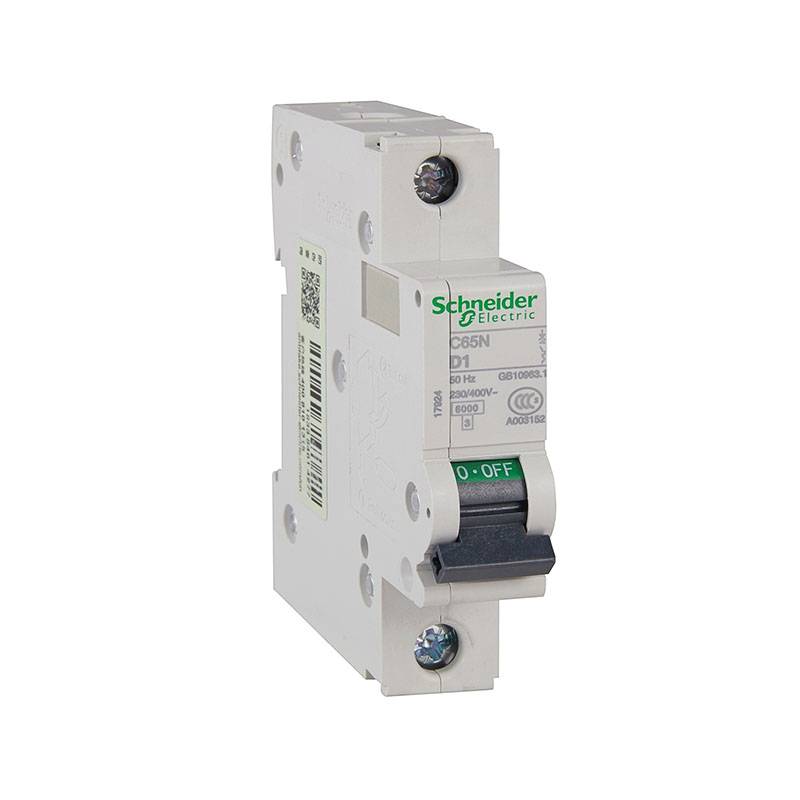
What does overcurrent protection guard against?
Overcurrent protection responds to two different kinds of excess current, and each requires a different part of the characteristic:
- Overload — a current moderately higher than the rated value (e.g. 1.2–3 × ), resulting from connecting too many loads. It builds up slowly and risks prolonged overheating of the insulation. It is handled by the overload region of the characteristic — operating with a delay that gets shorter as the current rises.
- Short circuit — a current many times higher than the rated value (from a few hundred amperes to several tens of kiloamperes), arising from a direct connection between conductors. It must be cleared very quickly. It is handled by the short-circuit region of the characteristic — operating practically instantaneously.
In a miniature circuit breaker (MCB) each of these ranges is handled by a separate element: thermal (bimetal) for overload and electromagnetic (coil) for short circuit. A gG cartridge fuse performs both functions with a single fuse-link whose time-current characteristic combines both ranges. A well-chosen protective device must correctly handle both scenarios: operate on overload before the cable overheats, and have a high enough breaking capacity to safely interrupt the largest possible short-circuit current.
Two overload conditions per PN-HD 60364-4-43
The standard PN-HD 60364-4-43 (protection against overcurrent) defines two conditions that must be met simultaneously for the protective device to protect the cable against overload:
where:
- — the design current of the circuit (the current actually drawn by the load),
- — the rated current of the protective device (the breaker setting or fuse value),
- — the continuous current-carrying capacity of the cable (the maximum current the cable carries without exceeding its limit temperature, after accounting for the installation method and correction factors),
- — the conventional operating current of the protective device, i.e. the current that ensures its operation within the conventional time (for a circuit breaker, read from the product standard; for a fuse, from the fuse-link characteristic).
The first condition is intuitive: the protective device must be "larger" than the load, but not larger than the cable's withstand. The second condition is often skipped, yet it is precisely the one that decides borderline cases — because depends on the type of device:
| Type of protective device | I₂ multiple | The condition I₂ ≤ 1.45·Iz reduces to |
|---|---|---|
Miniature circuit breaker MCB (PN-EN 60898) | I₂ = 1.45·Iₙ | Iₙ ≤ Iz (met automatically) |
gG cartridge fuse (PN-EN 60269) | I₂ = 1.6·Iₙ | Iₙ ≤ 0.91·Iz |
Practical conclusion: for an MCB the second condition is always met whenever the first one is — which is why for circuit breakers it is enough to check . For a gG fuse you additionally have to make sure that does not exceed about 91% of the cable's current-carrying capacity — otherwise the fuse-link may not operate quickly enough on a slight overload, even though formally .
The multiple of here applies to fuse-links with a current A. For smaller values the conventional operating current is higher — according to the table of conventional currents in PN-EN 60269-1 it is for A and for A — so the condition becomes even stricter (respectively and ). This is a common trap when protecting thin cables with small fuses.
Types of protection: MCBs, gG fuses and RCBOs
In low-voltage installations you will encounter three basic overcurrent protection solutions:
| Device | Characteristic | Typical use |
|---|---|---|
MCB circuit breaker (S301/S303) | Thermal-magnetic, reusable | Residential and general-purpose circuits |
gG cartridge fuse | Full-range, time-delayed; replaced after operating | Service connections, mains feeders, high short-circuit current circuits |
RCBO | MCB + residual current device in a single module | Individual circuits requiring residual current protection |
The gG fuse has two important advantages: a very high breaking capacity (up to 100 kA) and a favourable characteristic in the short-circuit band, which is why it is often used where short-circuit currents are high (close to the transformer). Its drawback is being single-use and the need to keep spare fuse-links in stock.
MCB characteristics: B, C and D
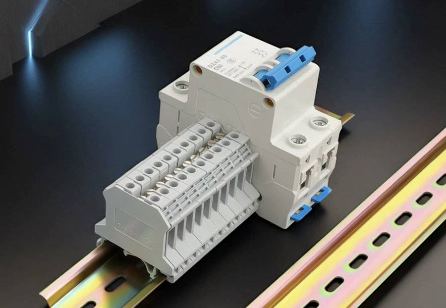
The letter in the breaker designation (e.g. C16) describes the magnetic tripping band — the multiple of the rated current at which the short-circuit element (instantaneous) operates. The choice of characteristic must match the load's inrush current: a characteristic that is too "sensitive" will cause nuisance tripping at switch-on, while one that is too "hard" may fail to provide shock protection.
| Characteristic | Magnetic operation | Use |
|---|---|---|
B | 3–5 × Iₙ | Lighting, socket outlets, resistive loads, long circuits |
C | 5–10 × Iₙ | Mixed circuits, motors, inductive loads, LED lighting with high inrush current |
D | 10–20 × Iₙ | Transformers, large motors, equipment with very high inrush current |
The upper limit of the magnetic band has a second, crucial meaning — it is the smallest current that guarantees instantaneous tripping. For characteristic B this is , for C — , for D — . This value is used when checking shock protection (see below). That is why the "harder" the characteristic, the greater the short-circuit current needed for fast tripping — and that is not always achievable at the end of a long circuit.
Short-circuit condition — breaking capacity
During a short circuit, the current flowing through the device is limited only by the impedance of the circuit from the source to the fault location. The protective device must safely interrupt this current without being destroyed. Hence the condition:
where is the rated breaking capacity of the device, and is the largest prospective short-circuit current at the point of installation (a three-phase or two-phase short circuit immediately downstream of the device). Typical values for MCBs are 6 kA (residential installations) and 10 kA (installations exposed to larger short circuits). gG fuses offer much higher values, which is why they are used close to the source.
Breaking capacity alone is not enough — the cable must also withstand thermally the energy let through by the protective device before it operates. In accordance with PN-HD 60364-4-43 (clause 434.5.2), the Joule integral of the short circuit must not exceed the conductor's permissible thermal energy:
where is the let-through specific energy of the protective device (from the data sheet), is the conductor cross-section, and is the material factor of the insulation (e.g. 115 for copper in PVC, 143 for XLPE). This condition matters especially for thin cables at high short-circuit currents — it is then the energy limit, not the current itself, that determines the permissible device.
Shock protection — will the device operate during an earth fault?
The second, "lower" end of the short-circuit problem is the smallest short-circuit current — usually a single-phase fault at the end of a long circuit. In accordance with PN-HD 60364-4-41, overcurrent protection simultaneously serves as shock protection through automatic disconnection of supply. The effectiveness condition is:
where is the fault loop impedance, is the line-to-earth voltage (230 V), and is the current that ensures disconnection within the required time. In a TN system at 230 V this time is 0.4 s for final circuits (socket outlets up to 63 A and fixed loads up to 32 A) and 5 s for distribution circuits and other final circuits. As a simplification, and a design-safe assumption, it is taken that the single-phase short-circuit current should exceed the upper limit of the magnetic band of the breaker — the value that guarantees instantaneous tripping (usually below 0.1 s):
If at the end of the circuit the single-phase short-circuit current is smaller than , the device will not trip instantaneously — it may still operate within the required time (e.g. 0.4 s) based on the manufacturer's time-current curve, but effectiveness must then be checked explicitly by reading off the tripping current for that time. The most reliable solutions are a "softer" characteristic (B instead of C), a larger cable cross-section (lower ), or the use of a residual current device which, for an earth fault (L–PE), ensures disconnection regardless of loop impedance — bearing in mind that an RCD does not protect against an L–N short circuit nor replace overcurrent protection.
Residual current devices RCD and RCBO
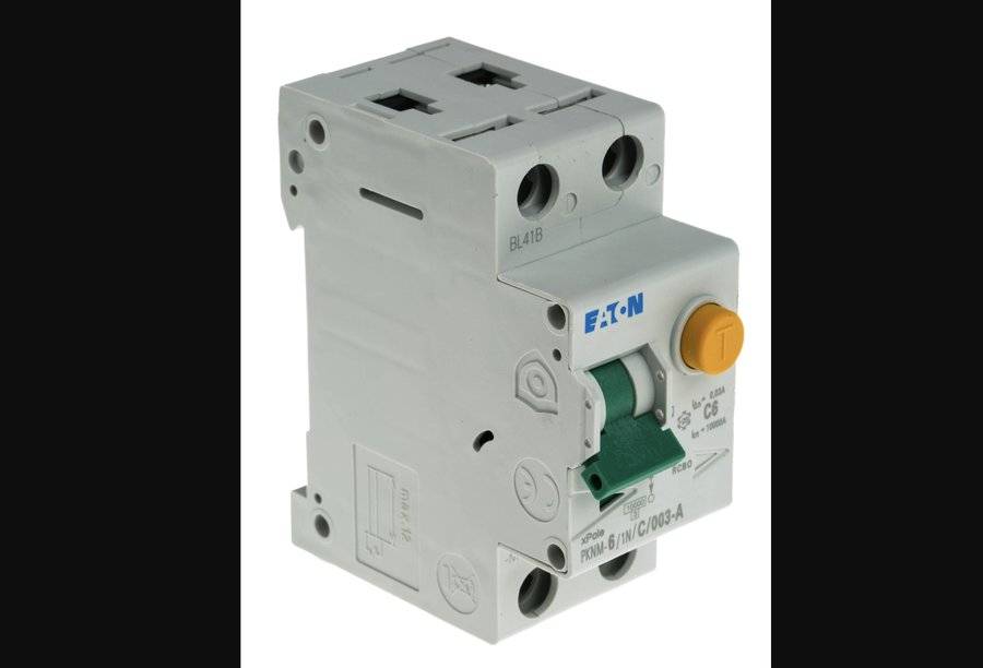
A residual current device (RCD) responds to the difference in currents in the live conductors — that is, to the current "leaking" to earth, e.g. through a person's body. It is supplementary protection to overcurrent protection, not a substitute for it. The standard requires an RCD with a residual current mA as additional protection, among others, for:
- socket outlets up to 32 A accessible to ordinary users,
- lighting circuits in residential premises (per PN-HD 60364-4-41:2017),
- circuits in rooms containing a bath or shower,
- portable loads up to 32 A used outdoors.
The type of RCD is important, matched to the shape of the residual current that may occur in the circuit:
| Type | Detects | Use |
|---|---|---|
AC | Sinusoidal alternating current | Purely resistive circuits (increasingly seldom recommended as the default) |
A | Alternating and pulsating direct current | Standard for circuits with electronics (sockets, washing machines, induction hobs) |
F | Like A + mixed-frequency currents | Circuits with inverters (washing machines, inverter air conditioners) |
B | Like F + smooth direct current | Electric vehicle chargers, PV inverters, DC stations |
Combining overcurrent and residual current protection in a single module gives an RCBO — convenient where you want the tripping of one circuit not to cut power to the others (unlike a shared RCD covering a group of circuits).
Selectivity of protective devices
In an extensive installation, protective devices form a cascade: the pre-meter device or the mains feeder protection sits "above" the protection of individual circuits. Selectivity means that during a short circuit in a final circuit, only the device closest to the fault trips, while the upstream one stays on. A difference in rated currents alone is not enough — selectivity, especially under short-circuit conditions, is confirmed on the basis of time-current characteristics, the Joule integrals and the manufacturer's coordination tables (e.g. a pre-meter gG fuse selective with respect to the circuit breakers). A lack of selectivity shows up when a minor short circuit in one room cuts power to the whole flat.
Step-by-step selection example
A general-purpose 230 V socket circuit, copper cable 3 × 2.5 mm² run in a conduit in the wall:
- Cable current-carrying capacity is read from the PN-HD 60364-5-52 tables for installation method B2 and PVC insulation — it depends on the number of loaded conductors: for a single-phase circuit (two loaded conductors) about 23–24 A, for three loaded conductors about 20 A. We take a conservative value A (and after applying correction factors — temperature, grouping — it may be lower).
- Design current of the load A.
- Selecting : we look for a device satisfying → standard choice MCB B16 or C16 ( A). The condition is met automatically for an MCB.
- Characteristic: a socket circuit with typical loads — B is sufficient (lower required short-circuit current, better shock protection). If the circuit serves equipment with high inrush current, C can be considered — but then shock protection must be re-checked.
- Short circuit: we check the breaking capacity (for a flat usually 6 kA, provided the calculated confirms this) and the cable's thermal withstand .
- Shock protection: for a B16, the required single-phase short-circuit current is A; we check whether at the end of the circuit is greater.
- RCD: a socket circuit → additional protection by a type A, 30 mA RCD/RCBO.
This is a simplified procedure — a full selection also includes checking , voltage drop and correction factors. All the standard's conditions (both overload, short-circuit and RCD selection) are verified by the overcurrent protection selection calculator. If you have not yet calculated the current-carrying capacity , start with the cable cross-section selection calculator and carry the result over to the protection selection.
Most common mistakes
- Skipping the second condition for gG fuses — is not enough; you need .
- Characteristic C where B would suffice — makes it harder to meet the shock-protection condition on long circuits.
- Breaking capacity too low in distribution boards close to the transformer.
- No 30 mA RCD on socket, bathroom and outdoor supply circuits.
- Wrong RCD type — type AC on circuits with inverters or an EV charger (type A, F or B is needed).
Summary
Selecting overcurrent protection is not picking a "round" value by rule of thumb, but meeting several conditions at once. The key principles:
- Check both overload conditions — and (for gG fuses the latter is decisive),
- Match the characteristic (B/C/D) to the load's inrush current,
- Verify the short circuit from several angles — breaking capacity against , the cable's thermal withstand and shock protection against ,
- Use a 30 mA RCD as additional protection and select the right type (A/F/B),
- Ensure selectivity in the cascade of protective devices.
Use the overcurrent protection selection calculator to match an MCB or gG fuse to a cable and check all the conditions of PN-HD 60364 in one place.
Back to articles list