
Electrical Cable Cross-Section Selection — Step-by-Step Guide According to N-SEP-E-002
12 marca 2026 | Electrical
Proper selection of an electrical cable cross-section is the foundation of a safe and efficient installation. A cable that is too thin risks overheating and even fire. A cable that is too thick is an unnecessary expense. In this guide, we will walk you through the entire selection process step by step, in accordance with the N-SEP-E-002 standard and the requirements of PN-HD 60364.
If you want to quickly select a cross-section without manual calculations, use our cable cross-section selection calculator. The calculator automatically accounts for current-carrying capacity, voltage drop, and temperature and grouping correction factors.
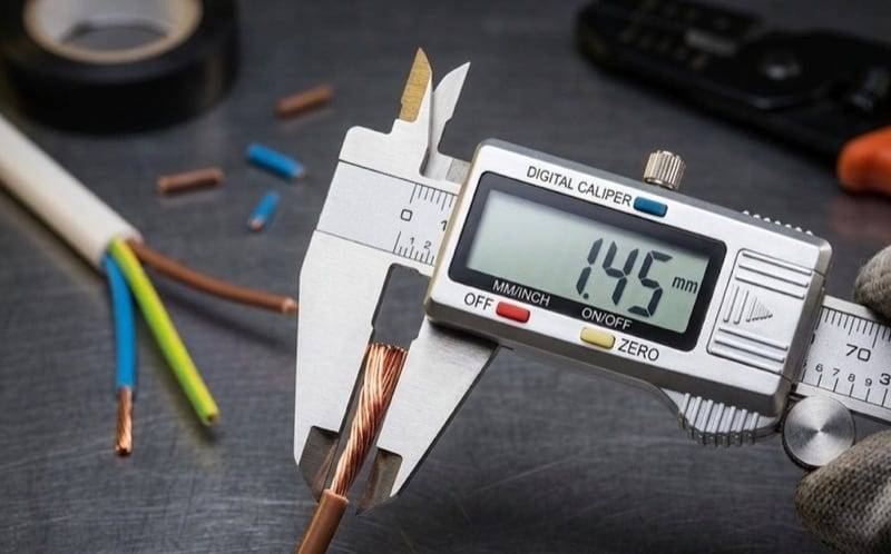
What is the N-SEP-E-002 standard?
The N-SEP-E-002 standard (Low-voltage electrical installations — Selection of cables for powering electrical equipment) is the primary document defining cable selection principles in Poland. This standard is based on the European IEC 60364-5-52 and specifies:
- the continuous current-carrying capacity of cables depending on the installation method,
- correction factors for ambient temperature and circuit grouping,
- permissible voltage drops in consumer installations.
Cable cross-section selection criteria
The cable cross-section must simultaneously meet two conditions:
- Current-carrying capacity condition — the load current must not exceed the permissible current-carrying capacity of the cable (corrected by correction factors).
- Voltage drop condition — the voltage drop across the cable must not exceed permissible values.
The more restrictive condition determines the cross-section — the one that requires a thicker cable.
Current-carrying capacity condition
The basic selection condition is:
where:
— load current (design current) [A]
— continuous current-carrying capacity from the table (reference conditions) [A]
— ambient temperature correction factor
— circuit grouping correction factor
— corrected current-carrying capacity [A]
Calculating the load current
The load current is calculated using the formula for a single-phase circuit (230 V):
and for a three-phase circuit (400 V):
where:
— device power [W]
— nominal voltage [V]
— power factor
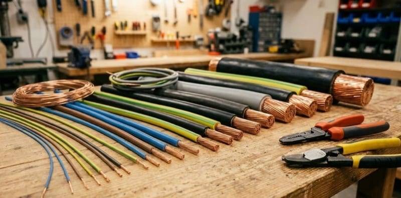
Typical power factor (cos φ) values
| Type of load | cos φ |
|---|---|
LED lighting, heaters | 0.95–1.0 |
Air conditioning, heat pumps | 0.85–0.90 |
Electric motors | 0.70–0.85 |
Welders | 0.50–0.70 |
Mixed load (residential) | 0.85 |
Installation methods (cable routing)
The cable installation method has a critical impact on its current-carrying capacity — a cable installed directly in open air dissipates heat much better than one embedded in a wall. The N-SEP-E-002 standard defines the following reference methods:
| Method | Description | Application example |
|---|---|---|
A1 | Cable in conduit in a thermally insulated wall | Concealed installation in an insulated wall |
A2 | Cable in conduit in a thermally insulated wall | Cable in protective conduit within insulation |
B1 | Cable in conduit on a wall | Concealed installation in a masonry wall |
B2 | Cable in conduit on a wall | Cable in protective conduit on a wall |
C | Cable directly on a wall | Cable fixed with clips on a wall |
E | Cable on a cable ladder | Cable route on a ladder in an industrial hall |
F | Cable on spaced brackets | Cable on brackets with clearance from the wall |
G | Freely suspended cable | Cable suspended on a catenary wire |
In residential construction, the most common methods are A1 and B1 (concealed installation). In industrial installations, methods E and F (cable routes) predominate.
Current-carrying capacity of copper (Cu) cables
The table below shows the continuous current-carrying capacity of copper cables with PVC insulation (reference temperature 30°C) for the most commonly used installation methods — for 3 loaded conductors (typical three-phase or single-phase installation with a protective conductor):
| Cross-section [mm²] | A1 [A] | B1 [A] | C [A] | E [A] |
|---|---|---|---|---|
| 1.5 | 13.5 | 15.5 | 17.5 | 18.5 |
| 2.5 | 18 | 21 | 24 | 25 |
| 4 | 24 | 28 | 32 | 34 |
| 6 | 31 | 36 | 41 | 43 |
| 10 | 42 | 50 | 57 | 60 |
| 16 | 56 | 68 | 76 | 80 |
| 25 | 73 | 89 | 96 | 101 |
| 35 | 89 | 110 | 119 | 126 |
| 50 | 108 | 134 | 144 | 153 |
| 70 | 136 | 171 | 184 | 196 |
These values apply to reference conditions: ambient temperature 30°C, single circuit (no grouping). For other conditions, correction factors must be applied.
Correction factors
Temperature correction factor (k₁)
The current-carrying capacity given in the tables applies to an ambient temperature of 30°C. If the actual temperature differs, the correction factor is applied:
| Ambient temperature [°C] | PVC (70°C) | XLPE (90°C) |
|---|---|---|
| 10 | 1.22 | 1.15 |
| 15 | 1.17 | 1.12 |
| 20 | 1.12 | 1.08 |
| 25 | 1.06 | 1.04 |
| 30 | 1.00 | 1.00 |
| 35 | 0.94 | 0.96 |
| 40 | 0.87 | 0.91 |
| 45 | 0.79 | 0.87 |
| 50 | 0.71 | 0.82 |
XLPE insulation is less sensitive to elevated temperatures than PVC, which is why in warm spaces (boiler rooms, attics) it is worth considering cables with XLPE insulation.
Grouping correction factor (k₂)
When several circuits are routed side by side (in the same conduit, trunking, or bundle), their mutual heating reduces the current-carrying capacity of each one:
| Number of circuits in a bundle | Factor k₂ | Capacity reduction |
|---|---|---|
| 1 | 1.00 | no reduction |
| 2 | 0.80 | –20% |
| 3 | 0.70 | –30% |
| 4 | 0.65 | –35% |
| 5 | 0.60 | –40% |
| 6 | 0.57 | –43% |
| 9 | 0.50 | –50% |
As you can see, with 9 circuits in a bundle, the current-carrying capacity drops by half! That is why in distribution boards and cable routes with a large number of circuits, thicker cables must be used.
Voltage drop condition
The second selection criterion is voltage drop. An excessive voltage drop causes improper operation of equipment — flickering lights, reduced motor power, or starting problems with devices.
Permissible voltage drops
The PN-HD 60364-5-52 standard specifies the following permissible voltage drop values in consumer installations:
| Supply source | Lighting | Other loads |
|---|---|---|
Type A — public network | 3% | 5% |
Type B — private source | 6% | 8% |
Voltage drop formula
For a single-phase circuit (simplified formula):
For a three-phase circuit:
where:
— load current [A]
— cable length [m]
— material conductivity [m/(Ω·mm²)]
— cable cross-section [mm²]
— nominal voltage [V]
Conductor material conductivity
| Material / Insulation | PVC [m/(Ω·mm²)] | XLPE [m/(Ω·mm²)] |
|---|---|---|
Copper (Cu) | 44.4 | 42.4 |
Aluminium (Al) | 27.5 | 26.3 |
The conductivity accounts for the operating temperature of the conductor (70°C for PVC, 90°C for XLPE), which is why these values are lower than the conductivity at 20°C.
To quickly check the voltage drop for any circuit, you can use our voltage drop calculator.
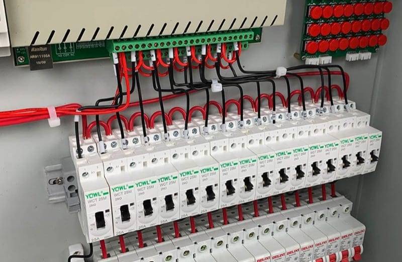
Copper or aluminium?
The choice of conductor material is one of the first questions when designing an installation. Both materials have their advantages:
Copper (Cu):
- higher conductivity (smaller cross-sections for the same currents),
- better flexibility and ease of handling,
- greater corrosion resistance,
- used in internal installations (mandatory for cross-sections ≤ 10 mm²).
Aluminium (Al):
- significantly lower cost for large cross-sections,
- lighter weight (important for long cable routes),
- used in supply lines and cables with cross-sections ≥ 16 mm²,
- requires special connectors (Al–Cu connections cause electrochemical corrosion).
In residential installations and small buildings, copper is the standard. Aluminium is mainly used in building supply lines and in industrial installations with large cross-sections.
PVC or XLPE — choosing insulation
The type of insulation affects the permissible operating temperature of the conductor, and thus its current-carrying capacity:
- PVC (polyvinyl chloride) — permissible continuous conductor temperature: 70°C. Cheaper, commonly used in internal installations.
- XLPE (cross-linked polyethylene) — permissible continuous conductor temperature: 90°C. Higher current-carrying capacity (15–25% more than PVC for the same cross-section), better resistance to temperature and moisture.
Standard cable cross-sections
Cable cross-sections are standardised. Available cross-sections in mm²:
1.5 — 2.5 — 4 — 6 — 10 — 16 — 25 — 35 — 50 — 70 — 95 — 120 — 150 — 185 — 240
Typical applications in residential installations:
- 1.5 mm² — lighting circuits (B10 circuit breaker)
- 2.5 mm² — socket outlet circuits (B16 circuit breaker)
- 4 mm² — electric cookers, ovens (B25 circuit breaker)
- 6 mm² — induction hobs, smaller heat pumps (B32 circuit breaker)
- 10 mm² — sub-distribution board supply, larger loads (B40–B50 circuit breaker)
- 16 mm² and above — supply lines, main distribution lines
Practical example — step-by-step selection
Let us select a cable to supply an electric cooker with the following data:
- Power: P = 7,000 W
- Supply: single-phase 230 V
- Power factor: cos φ = 0.95
- Cable length: L = 20 m
- Material: copper (Cu), PVC insulation
- Installation method: B1 (cable in conduit, concealed)
- Ambient temperature: 30°C (reference conditions)
- Number of circuits in a bundle: 3
- Supply source: public network (type A), non-lighting load
Step 1: Calculating the load current
Step 2: Correction factors
- Temperature 30°C → = 1.00 (reference conditions)
- 3 circuits in a bundle → = 0.70
Step 3: Checking current-carrying capacity
We look for a cross-section where: A
Current-carrying capacity of Cu/PVC/B1 cables (3 loaded conductors):
| Cross-section [mm²] | Iz0 [A] | Iz = Iz0 · 0.70 [A] | Iz ≥ 32.0 A? |
|---|---|---|---|
| 4 | 28 | 19.6 | No |
| 6 | 36 | 25.2 | No |
| 10 | 50 | 35.0 | Yes |
| 16 | 68 | 47.6 | Yes |
Based on the current-carrying capacity condition, the minimum cross-section is 10 mm².
Step 4: Checking the voltage drop
Let us check the voltage drop for a 10 mm² cross-section:
Permissible voltage drop: 5% (public network, non-lighting load).
Calculated drop 1.25% ≤ 5% — condition satisfied.
Step 5: Selection result
| Selected cross-section | 10 mm² |
|---|---|
| Corrected current-carrying capacity | 35.0 A |
| Load current | 32.0 A |
| Voltage drop | 1.25% |
| Determining condition | current-carrying capacity |
| Recommended circuit breaker | B32 |
Without grouping (single circuit), a 6 mm² cross-section would have been sufficient (current-carrying capacity 36 A > 32 A). Grouping of 3 circuits required increasing the cross-section to 10 mm² — this is a common situation in practice.
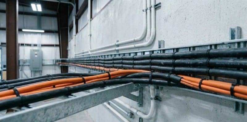
Most common cable selection mistakes
-
Ignoring the grouping factor — a distribution board may have a dozen circuits in a single trunking. Without accounting for , the cables will overheat.
-
Not considering cable length — for short circuits (up to 10 m), the voltage drop is usually negligible. But for long routes (30–50 m and more), the voltage drop may require a thicker cable than indicated by the current-carrying capacity alone.
-
Selecting "from memory" — applying the rule "2.5 mm² for sockets, 1.5 mm² for lighting" without verifying the actual load and installation conditions.
-
Not accounting for ambient temperature — a cable routed through an attic in summer may operate at 40–50°C. With PVC at 50°C, the current-carrying capacity drops by 29%!
-
Incorrect installation method determination — a cable in a conduit in an insulated wall (A1) has a significantly lower current-carrying capacity than the same cable on a cable ladder (E).
When does voltage drop determine the cross-section?
Voltage drop becomes the determining condition mainly when:
- the cable length exceeds 30–40 m — typical for supplying outbuildings, garages, outdoor lighting,
- the load power is high — e.g., workshop supply, electric sauna,
- lighting circuits — the permissible voltage drop is only 3% (supply from public network),
- aluminium cables — lower conductivity means a greater voltage drop for the same cross-section.
In such cases, our cable cross-section selection calculator will automatically indicate which condition (current-carrying capacity or voltage drop) is the determining one.
Summary
Proper cable cross-section selection requires:
- calculating the load current based on power and voltage,
- accounting for correction factors for temperature () and grouping (),
- checking the current-carrying capacity from the N-SEP-E-002 standard tables,
- verifying the voltage drop (max 3% for lighting, 5% for other loads when supplied from the public network),
- choosing the larger cross-section if the conditions yield different results.
You can perform this entire process automatically using our electrical cable cross-section selection calculator. Simply enter the power, voltage, length, and installation conditions — the calculator will select the optimal cross-section and display a comparison with adjacent cross-sections. You can also save your calculations as a cable selection project to return to them later.
Back to articles list