
How to Design an Electrical Switchboard — a Step-by-Step Guide
19 lipca 2026 | Electrical
A switchboard design does not start with a drawing of the enclosure — it starts with the list of circuits. That list determines how many protective devices you need, how large the enclosure has to be and how the load is spread across the phases. Below we walk through the whole process step by step: from building the circuit list, through selecting the miniature circuit breakers and residual current devices, to the enclosure size, the single-line diagram and the bill of materials.
Quick answerA switchboard is designed in five steps: (1) build the list of final circuits, (2) for each one select the protective device — an MCB, and for residual current protection an RCD or RCBO, (3) work out the enclosure size: the sum of modules of all devices, increased by a reserve and rounded up to a row of 12/18 modules, (4) distribute the single-phase circuits evenly across phases L1/L2/L3, (5) prepare the documentation: the front layout, the single-line diagram and the bill of materials. The basic condition for selecting a protective device is .

What is a switchboard and what does its design cover?
A low-voltage switchboard is the heart of the installation: every final circuit runs out from it and all the protective devices are mounted inside it. A typical set of devices is:
- main isolator (isolating switch) — disconnects the entire switchboard,
- surge protective device (SPD) — protection against atmospheric and switching overvoltages,
- residual current devices (RCDs) or RCBOs — supplementary protection against electric shock,
- miniature circuit breakers (MCBs) — protection of each circuit's cables,
- busbars (PE, N), terminals and comb busbars.
A complete switchboard design is more than just a list of devices. It is made up of four elements: the circuit list, the front layout (arrangement of devices on the rails), the single-line diagram and the bill of materials (BOM). In a well-run design all four derive from one source — the circuit list.
Step 1 — Build the circuit list
Start by listing all the final circuits. For each one determine: the purpose, the number of phases (single-phase 230 V or three-phase 400 V) and the design current . In a residential installation it is convenient to work with typical circuits: general socket outlets, kitchen circuit, induction hob, lighting, bathroom, washing machine and dishwasher, boiler-room circuit, electric vehicle charger.
This is the circuit list and the assumptions for the switchboard — not a full load calculation for the installation. If you first need to determine the demand and select the pre-meter protective device, do that separately in the load calculation guide, and come into the switchboard with a ready circuit list.
Step 2 — Select the protective devices (MCB, RCD, RCBO)
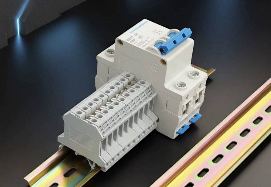
Every final circuit has overcurrent protection — either a standalone MCB or an MCB integrated into an RCBO. For residential circuits a type B characteristic is used; a type C characteristic (a higher operating current of the magnetic element) is sometimes needed for loads with a high inrush current — but that is a design decision, not a "just in case" swap (we come back to it in the section on mistakes).
Supplementary protection against electric shock is provided by RCDs with a 30 mA sensitivity. Their type is crucial:
| Circuit type | MCB | RCD type |
|---|---|---|
| General socket outlets, lighting | B | A |
| Washing machine, dishwasher, induction hob | B | A |
| EV charger | B / C | B or A + 6 mA DC detection |
| PV inverter, energy storage | per documentation | per inverter documentation |
In typical new domestic installations type A is used — it responds to alternating and pulsating direct leakage currents produced by equipment with electronics; type AC (alternating current only) is generally no longer chosen today for circuits with electronics. Ultimately the RCD type is matched to the expected leakage current and the load's documentation. For devices with a single-phase converter (some washing machines, heat pumps) type F may be the right choice. EV chargers are a separate case — they require the charging point to be protected by at least type A with 6 mA DC detection (RDC-DD per IEC 62955) or by type B, depending on whether the charger itself (the EVSE) has built-in DC detection (PN-HD 60364-7-722). The RCD type for a PV inverter is dictated by its documentation and its method of connection.
The condition for selecting the overcurrent protective device relative to the cable is:
where is the circuit's design current, is the breaker's rated current, and is the cable's current-carrying capacity. For MCBs to PN-EN 60898-1 the second coordination condition is met automatically once you keep (because for an MCB ). We do not expand on selecting the current-carrying capacity and the cross-section here — but you can read more in the overcurrent protection selection guide.
Group RCDs or an RCBO per circuit?
This is the most common architectural decision in a switchboard:
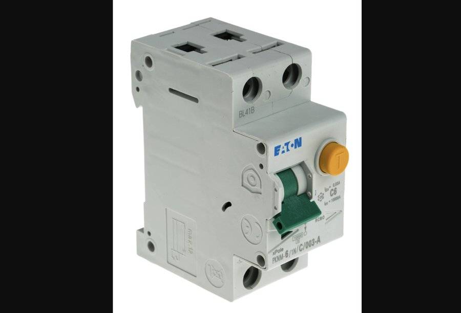
- Group RCDs — one 30 mA RCD for several circuits with individual MCBs. Cheaper, fewer modules, but tripping the RCD kills the whole group.
- An RCBO per circuit — a fault on one circuit does not switch off the others (better supply continuity), but it costs more and takes more modules. It limits the consequences of a fault to a single circuit, it is not a guarantee of full selectivity with the upstream device.
In practice the two are combined: RCBOs for critical circuits (fridge, boiler room, EV charger), group RCDs for the rest. If you group circuits behind one RCD, the neutral conductor is crucial — the N of each circuit must return through the same RCD that protects it. A 2-pole RCD will handle a group of single-phase circuits on one phase; a 4-pole RCD is intended for a three-phase load. Technically a 4-pole device can also cover a group of single-phase circuits spread across L1/L2/L3 (as long as the neutrals of all those circuits pass through that RCD), but in practice this is avoided: a fault on one circuit then switches off all three phases, and damage to the N path inside the device risks an elevated voltage appearing on the single-phase loads.
Step 3 — Select the enclosure: how many modules and how much reserve?
The width of modular devices is measured in modules: 1 module = 17.5 mm. Enclosures most often have rows of 12 or 18 modules. You calculate the number of modules from the total width of all devices — the main isolator, the SPD, the RCDs, the RCBOs and the MCBs — not just the miniature circuit breakers:
where is the space reserve. Good practice is 20–30% depending on the anticipated expansion. You round the result up to the enclosure capacity — that is, to whole rows. You also have to allow room for busbar terminals and distribution blocks, as well as the mounting clearances needed for heat dissipation (when tightly packed, devices heat one another, which lowers their real rated current).
The enclosure's IP rating is determined by the environmental conditions at the mounting location — from IP30 in a dry interior (e.g. a hallway), through IP44–IP55 in damp or dusty rooms, to IP65 outdoors.
Step 4 — Phase balancing in a three-phase installation
If the switchboard is fed from three phases, distribute the single-phase circuits as evenly as possible across phases L1, L2 and L3. The goal is to avoid load asymmetry — a situation where one phase is overloaded while the other two are almost empty. An uneven distribution loads the neutral conductor and worsens the installation's operating conditions.
Step 5 — Documentation: single-line diagram, front layout and BOM
A finished switchboard design consists of three documents:
- Single-line diagram — shows the supply path, for example: supply → main isolator → SPD → RCDs → circuits with miniature circuit breakers, labels and phase assignments (the specific arrangement, including the SPD connection, depends on the earthing system and the manufacturers' instructions). This is the most sought-after part of switchboard documentation.
- Front layout — a view of the device arrangement on the DIN rails, keeping each residual current group intact.
- Bill of materials (BOM) — a list of devices and the enclosure with catalogue numbers.
This is the most labour-intensive, "drawing" part of the design — and it is where an online tool saves the most time.
The most common switchboard design mistakes
- No space reserve. An enclosure filled to the brim leaves no room to add a circuit or terminals. Leave 20–30%.
- Swapping an MCB from B to C "blindly". A type C characteristic only trips its magnetic element at 5–10 times the rated current (type B: 3–5 times), so it requires a lower earth fault loop impedance to meet the automatic disconnection condition. Changing it without checking can leave the circuit without effective protection against electric shock.
- The wrong RCD type for electronics. Type AC on a washing machine, induction hob or dishwasher is a bad choice — at least type A is needed. An EV charger requires separately selected protection (type A with 6 mA DC detection or type B), and a PV inverter — protection that matches its documentation.
- One overloaded phase in a three-phase installation — see phase balancing.
- No circuit labels on the front layout and diagram — this hinders acceptance and later operation.
What the planner does not verifyThe planner supports selecting and arranging the devices and prepares the assembly documentation — but it does not replace the installation design. Outside its scope remain: selecting cable cross-sections, checking the voltage drop, verifying the automatic disconnection condition (earth fault loop impedance ), selecting the surge protective device (type 1+2, method and length of connection), earthing, protection selectivity and the connection conditions. Installation, wiring and acceptance testing must be carried out by a suitably qualified electrician.
Design your switchboard in the planner
Instead of drawing the front layout and diagram by hand, build the circuit list in the switchboard planner — and the front layout, the single-line diagram and the bill of materials will be created automatically. The tool runs in the browser without a login, and the project is saved locally. An account (with a 5-day free trial, no card) only becomes useful for saving the project in the cloud and downloading the documentation as a PDF.
Frequently asked questions (FAQ)
Where do you start when designing an electrical switchboard? With the list of final circuits — it is the source of truth for the whole switchboard. For each circuit you decide the purpose, the number of phases and the design current. Only then do you choose the protective devices, the enclosure size and draw the diagram.
How many circuits and modules should a residential switchboard have? It depends on the number and type of circuits, not on the floor area. You add up the width of all devices in modules (1 module = 17.5 mm), add room for terminals and a 20–30% reserve, and round the result up to the enclosure capacity (rows of 12 or 18 modules).
What is the difference between an MCB, an RCD and an RCBO? An MCB protects the cable against overload and short circuit. An RCCB (residual current circuit breaker) detects earth leakage current and protects people, but it does not protect the cable — which is why it always works together with an overcurrent device (an MCB or a fuse). An RCBO combines both functions in a single device and works on its own.
When should you use a type A RCD and when a type B? In new domestic installations type A is used almost universally; ultimately the type is matched to the nature of the load and its documentation. An EV charger requires at least type A with 6 mA DC detection (RDC-DD) or type B — depending on whether the charger itself has built-in DC detection (PN-HD 60364-7-722). The type for a PV inverter is dictated by its documentation.
Group RCDs or an RCBO per circuit? Group RCDs are cheaper, but tripping the RCD kills the whole group. An RCBO limits the trip to a single circuit (better supply continuity) at the cost of space and price — but it is not a guarantee of full selectivity with the upstream device. In practice both are combined: RCBOs for critical circuits, group RCDs for the rest.
Do you need CAD software to design a switchboard? No. The online switchboard planner generates the front layout, the single-line diagram and the bill of materials from the circuit list, without installing software and without an account.
Does a switchboard design in the planner replace an installation design? No. The planner supports selecting the devices and prepares the assembly documentation, but it does not replace selecting cross-sections, checking , selecting the SPD, earthing and selectivity. Installation and acceptance testing are carried out by a qualified electrician.
Back to articles list