
Designing building sanitary drainage per PN-EN 12056-2
22 kwietnia 2026 | Sewerage
Incorrect sizing of a sanitary drainage system leads to blockages, backflow, water hammer and noise transmitted to habitable rooms — and, in extreme cases, to flooding of storeys located below the flood level. This guide covers the complete design methodology for internal sanitary drainage in a building in accordance with PN-EN 12056-2:2002 and the Polish Regulation on the technical conditions to be met by buildings and their location. We focus on branch discharge pipes, discharge stacks and drainage pipes within the building envelope.
If you need to quickly size a sanitary drainage system based on fixtures and the type of building use, use our sanitary drainage calculator. Hydraulic calculations of gravity pipes outside the building (Manning's formula, filling levels, external gradients) are discussed separately in the article Hydraulic calculations of gravity sewer pipes.
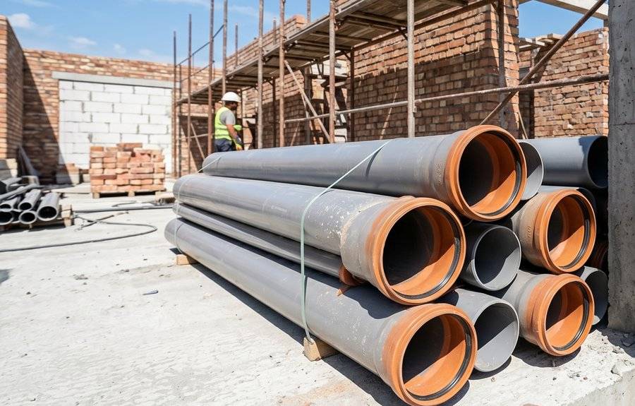
Legal and standard basis
Sanitary drainage design in Poland relies on several mutually complementary acts:
- PN-EN 12056-2:2002 — Gravity drainage systems inside buildings. Part 2: Sanitary pipework, layout design and calculation. The primary standard for pipe sizing.
- PN-EN 12056-3:2002 — Part 3: Roof drainage inside buildings. Outside the scope of this article.
- Regulation of the Minister of Infrastructure on the technical conditions (Journal of Laws 2022 item 1225, as amended), §122–§128 — general requirements for building drainage.
- PN-92/B-01707 — Drainage installations. Design requirements. A historical method, still quoted in many Polish design offices.
- PN-EN 13564 — backflow prevention devices.
- PN-EN 12050-1/2 — wastewater lifting plants.
- PN-EN 1825 / PN-EN 858 — grease and oil separators.
Current thermal and installation requirements of the Technical Conditions regulation are described in the article New Technical Conditions 2026.
Wastewater discharge systems per EN 12056-2
The European standard defines four systems that differ in the way branches are routed and in the permissible filling degree. The choice of system determines stack capacity values and DU tables.
| System | Description | Max. filling h/D | Typical countries |
|---|---|---|---|
| I | Single stack, partially filled branch discharge pipes | 0,5 | Poland, Germany, Austria |
| II | Single stack, small-bore branch discharge pipes, full flow | 0,7 | United Kingdom |
| III | Single stack, fully filled branch discharge pipes | 1,0 | France |
| IV | Separate stacks for grey and black water | per I–III | Mixed systems |
In Polish design practice the standard is System I. In the remainder of this article, all capacity values and limitations refer to this system — unless explicitly stated otherwise.
Discharge units (DU) — the calculation basis
DU definition
Discharge Unit (DU) is the standardised discharge flow of a sanitary fixture expressed in . It is neither an instantaneous nor an average flow — it is a conventional statistical value that allows the contribution of many fixtures to be aggregated into a single number characterising a section of the installation. Thanks to this, summing DU from successive storeys and combining them in the stack makes sense regardless of the synchronisation of real-life use.
Table of DU and minimum branch discharge pipe diameters
DU values per table 2 of PN-EN 12056-2 for System I. Minimum branch discharge pipe diameters consistent with common Polish design practice:
| Sanitary fixture | DU [l/s] | Min. DN of branch |
|---|---|---|
| Washbasin, bidet | 0,5 | 40 |
| Shower tray | 0,6 | 50 |
| Bathtub | 0,8 | 50 |
| Kitchen sink | 0,8 | 50 |
| Dishwasher or washing machine up to 6 kg | 0,8 | 50 |
| Washing machine up to 12 kg | 1,5 | 50 |
| Urinal with flushing valve | 0,5 | 50 |
| Urinal with flushing cistern | 0,8 | 50 |
| WC pan with 6 l cistern | 2,0 | 100 |
| WC pan with 9 l cistern | 2,5 | 100 |
| Floor gully DN 50 | 0,8 | 50 |
| Floor gully DN 70 | 1,5 | 70 |
| Floor gully DN 100 | 2,0 | 100 |
Two practical issues where designers most often make mistakes:
- For a dishwasher connected to the sink trap we do not sum DU — we take the greater value of the two fixtures.
- For water-saving 4 l / 2 l WC pans the standard does not provide a dedicated value. In practice 1,8 DU is used or — for safety — 2,0 DU is retained as for a 6 l pan.
Frequency factor K
Discharges from different fixtures do not occur simultaneously — if they did, pipe diameters would have to be absurdly large. The standard introduces the frequency factor K, which models this non-simultaneity statistically.
Design flow rate formula
Where:
- — design sanitary wastewater flow rate ,
- — frequency factor dependent on the type of building use,
- — sum of discharge units of all fixtures feeding the section under consideration.
The square root in this formula is an empirical-statistical relationship from the standard — it reflects the fact that the instantaneous flow grows much more slowly than linearly with the number of fixtures, because the probability of their simultaneous use decreases.
K values
| Use type | K | Example buildings |
|---|---|---|
| Intermittent | 0,5 | Dwellings, guesthouses, offices |
| Regular | 0,7 | Hospitals, schools, restaurants, hotels |
| Frequent (public) | 1,0 | Public toilets, communal showers |
| Special | 1,2 | Laboratories, industrial facilities |
Qmin rule and additional flows
A critical condition: if the calculated is smaller than the largest single DU on the section, we adopt that largest DU value for further calculations. The reason is simple — the system must accept the instantaneous discharge from a single fixture, even if the statistics of simultaneity show a smaller average flow. This error is common in small single-family installations.
To the sanitary flow we add constant and continuous flows in accordance with section 6.5.2 of the standard:
Where represents continuous flows (e.g. discharges from air conditioning, water treatment systems, chillers) and represents pumped flows. Omitting in office buildings with central cooling is the second typical mistake — condensate from the evaporator can generate a continuous stream of the order of 0,1–0,3 l/s per storey.
Do you need to perform this calculation for a specific list of fixtures? The sanitary drainage calculator does it automatically — you select the use type, add fixtures, and get and the minimum diameter.
Sizing: branch discharge pipes, stacks, drainage pipes
Branch discharge pipes
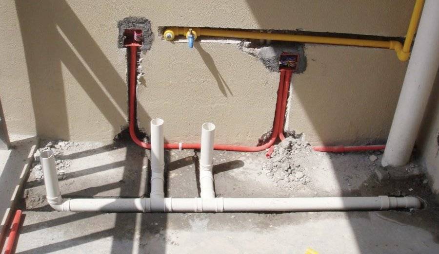
A branch discharge pipe is the section from the fixture trap to the stack. Sizing rules:
- The diameter must not be smaller than the diameter of the largest fixture connected to the branch.
- Venting of branches. An unvented branch discharge pipe is permissible only up to a limited length, gradient and number of bends (table 5 of PN-EN 12056-2). In System I, for DN 50–100 branches, generally maximum 4 m is assumed (with a limited number of 90° bends). Exceeding these values forces secondary venting or use of an air admittance valve. This is the most common source of installation errors leading to water seal siphoning.
- Minimum gradients: 2–3% for DN 50, 1,5% for DN 100, 1% for DN 150.
- Maximum number of 90° bends on a branch — per table 5 of the standard.
Discharge stacks
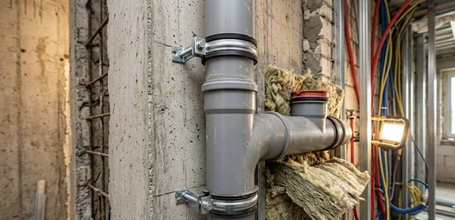
Stack capacity depends on the system, diameter, venting method and the type of branch entries to the stack. Table 11 of PN-EN 12056-2 distinguishes square entries (fittings at an angle of 87–88°) and swept entries (45° fittings with a longitudinal profile) — the latter provide higher capacity. Below are values for System I with a vent stack extended above the roof; in design work the safer values for square entries are most often adopted:
| Stack DN | Qmax square entry [l/s] | Qmax swept entry [l/s] |
|---|---|---|
| 70 | 1,5 | 2,0 |
| 90 | 2,7 | 3,5 |
| 100 | 4,0 | 5,2 |
| 125 | 5,8 | 7,6 |
| 150 | 9,5 | 12,4 |
Additional rules:
- The stack must not be smaller than the largest branch connected to it. For a WC pan this means minimum DN 100 — a standard requirement, not just Polish practice.
- The vent stack extended above the roof must have a diameter not smaller than the discharge stack (reduction to 50 mm is permissible in the non-freezing zone).
- Air admittance valves (AAV) — used where the stack cannot be extended above the roof. They let air into the stack under negative pressure, but do not release positive pressure from the lower sections. They are therefore not a full replacement for a roof vent and should be treated as a supplementary solution or used to a limited extent — in accordance with the manufacturer's recommendations and the conditions of the standard. In multi-storey buildings, a roof vent at least for the main stack is required.
Horizontal drainage pipes in the building
These are the collecting horizontal pipes in the basement / under the ground floor slab carrying wastewater from stacks to the building drain. Sizing rules:
- Maximum filling for System I.
- Design gradients used in Polish design office practice:
| DN | Design gradient | Min. hydraulic gradient |
|---|---|---|
| 100 / 110 | 2,0% | 1,5% |
| 150 / 160 | 1,5% | 1,0% |
| 200 | 1,0% | 0,7% |
In projects the values from the "design gradient" column are adopted — the hydraulic minima show the calculation limit resulting from the requirement, but in practice they are reserved only for situations forced by building geometry.
- Self-cleansing velocity: , . Below sediment builds up and solids settle out; above splashing, breaking of water seals and pipe wall erosion appear.
- Detailed hydraulic calculations of underground horizontal pipes outside the building — see the article Hydraulic calculations of gravity sewer pipes (Manning's formula).
Worked example — multi-family residential building
A four-storey building, 2 flats per floor. Standard fixture set in each flat: WC 6 l, washbasin, bathtub, kitchen sink, washing machine 6 kg.
Step 1. DU sum on the stack
Per flat:
The stack serves 8 flats:
Step 2. Design flow rate
Residential building → intermittent use, :
Check the Qmin rule: the largest single DU = 2,0 (WC pan). — condition satisfied, we use .
Step 3. Stack sizing
From the capacity table (square entries): DN 90 gives Qmax = 2,7 l/s — not enough. We select DN 100 (Qmax = 4,0 l/s, reserve ~28%). Regardless of the arithmetic, the stack must accommodate a WC pan — the minimum branch is DN 100, so DN 100 is also the lower standard limit.
Step 4. Building drain sizing
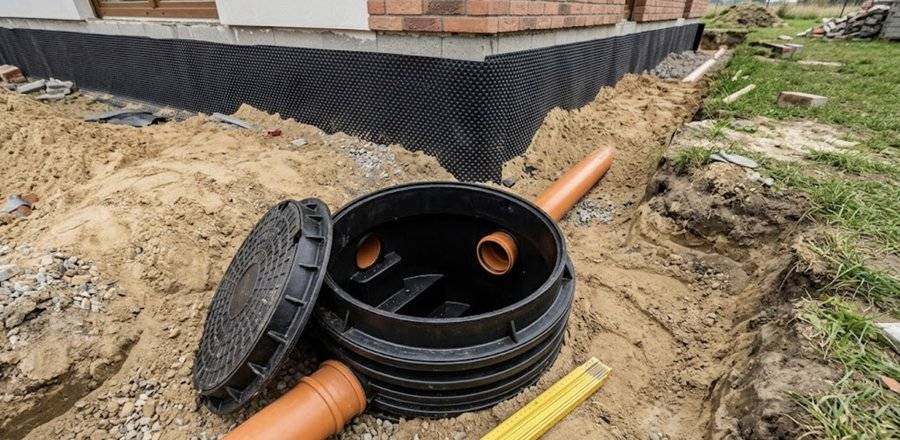
The building drain (the pipe under the building from the last stack to the chamber at the plot boundary) in this example serves one stack, so for design purposes . At a gradient of 1,5% and filling of 0,5 with the requirement we select DN 150 with a large reserve (Manning calculations in the article on gravity drainage). If the building drain collects more stacks, we compute from the sum of DU from all stacks (we do not add Qww from individual stacks arithmetically — the statistical simultaneity still applies).
The same calculation in 30 seconds — the sanitary drainage calculator performs it automatically once you select the use type and add the fixtures.
Backflow prevention devices and lifting plants
Backflow protection (PN-EN 13564)
Every sanitary fixture below the flood level (the level up to which water can flow back from the sewer network — in practice usually the ground level at the nearest inspection chamber) must be protected against backflow. This is a requirement of the Technical Conditions regulation.
Basic solutions:
- Raising the installation above the flood level (lifting plant with a backflow loop). Wastewater from fixtures below the flood level is lifted by a pump, and the pressure pipe is routed above the flood level before entering the gravity drainage. This approach is absolutely required for fixtures with faecal matter in permanently used buildings.
- Backflow prevention devices per PN-EN 13564 — fittings installed in the drainage pipe which close automatically during backflow. Used for buildings with limited risk and for fixtures that can be temporarily taken out of service during backflow.
PN-EN 13564-1 classifies backflow prevention devices into five types differing in design (including the number of flaps, presence of a weighted flap, manual safety closure) and intended use — from linear drainage without faecal matter to installations carrying faecal matter. The type is selected according to the type of wastewater and the required level of safety.
Wastewater lifting plants (PN-EN 12050)
When sanitary fixtures are located below the gravity discharge level, a lifting plant is required:
- PN-EN 12050-1 — lifting plants for wastewater containing faecal matter (black water). Underground garages with WCs, basements with sanitary rooms. Minimum pressure pipe diameter DN 80.
- PN-EN 12050-2 — lifting plants for wastewater without faecal matter (grey water). Shower tray pumps, basement laundries. Minimum pressure pipe diameter DN 32.
Pump sizing: capacity ≥ on the pumped section, geometric lift head + linear and local pressure losses. For black-water lifting plants, two units (100% redundancy) are required in multi-family residential and public buildings.
Separators
- Grease separators (PN-EN 1825) — mandatory in catering facilities: restaurants, canteens, hotel kitchens, hospital kitchens. Sized according to nominal size NS (expressed in l/s), depending on the number of meals, wastewater temperature and presence of detergents.
- Oil separators (PN-EN 858) — underground car parks, filling stations, car washes, mechanical workshops. Class I (≤ 5 mg/l at the outlet) — for facilities discharging to surface waters, class II (≤ 100 mg/l) — to combined sewers.
- Starch separators, sand traps — food processing plants, ceramic workshops.
Acoustic and fire protection aspects
Drainage installation noise
A discharge stack routed in a shaft next to a habitable room wall generates noise from two sources: the falling wastewater stream and the transmission of vibrations to the structure. DIN 4109 requirements (used in Poland as a benchmark) — maximum 30 dB(A) in a room adjacent to the stack.
Selection of materials and fixings:
- Fixing with clamps with an EPDM insert — mandatory for stacks in residential buildings. Eliminates direct metal-to-concrete contact.
- Pipe materials ranked from quietest: SML cast iron ≈ 15 dB(A) → silent PP with mineral filler ≈ 17 dB(A) → standard PP HT ≈ 25 dB(A) → PVC-U ≈ 28 dB(A).
- A stack in a shaft with acoustic lining and mineral wool additionally reduces transmission by 5–10 dB(A).
For more on acoustic insulation of partitions and standard requirements — Acoustic insulation Rw — a guide.
Penetrations through fire barriers
Every drainage pipe passing through a barrier with a required fire resistance class (EI 30, EI 60, EI 120) must preserve the class of that barrier. Basis: Technical Conditions §232 and PN-EN 1366-3.
Solutions used:
- Fire protection collars (intumescent wraps) — mounted on the pipe on the unexposed side. In a fire they expand, closing the pipe bore after it melts.
- Intumescent sleeves — built into the barrier around the pipe.
- Fire protection mortars — for sealing gaps between pipe and barrier.
Selected according to the barrier's resistance class, pipe diameter and material (PVC vs PP vs cast iron). Non-compliance is one of the most common reasons for a negative acceptance of the installation by the fire brigade.
Drainage pipe materials
The choice of material affects durability, thermal resistance, acoustics and cost:
- PVC-U (solid grey pipes) — internal low-temperature drainage, standard for residential stacks.
- PP (HT) — resistance to high temperatures up to 90 °C briefly; required for washing machine and dishwasher branches. More in: polypropylene pipes.
- Silent PP with mineral filler — vertical runs in residential buildings where acoustic requirements are increased.
- SML cast iron — facilities requiring the highest fire and acoustic resistance (hotels, healthcare facilities).
Briefly on PVC for external and underground drainage: PVC pipes.
Common design mistakes
- Gradients too small for DN 100 pipes (< 1,5%) — lead to particle deposition, odours and blockages within several years of operation.
- No or insufficient stack venting — results in water seal siphoning and odours penetrating rooms.
- Connecting a WC pan to a DN 70 or DN 90 stack — the minimum branch for a WC is DN 100, so the stack cannot be smaller either.
- Omitting floor gullies from the DU balance at the technical level (garages, laundries, basements).
- Mixing systems — using System III capacity values for a layout built as System I.
- Diameter reductions in the flow direction — not permitted in gravity drainage. The diameter must be constant or increase in the flow direction; any reduction always leads to backing up.
- Omitting continuous flows Qc from air conditioning, water treatment, chillers.
- Treating an air admittance valve (AAV) as a full replacement for a roof vent — an AAV does not release positive pressure; in multi-storey buildings a roof vent is required at least for the main stack.
- Lack of a backflow prevention device or a lifting plant with a backflow loop for fixtures below the flood level — exposes basements to backflow from the network.
- Non-compliant fire-rated penetrations — rejected at acceptance.
Summary
Designing an internal building drainage system comes down to five steps:
- Sum the discharge units DU for all fixtures on the section.
- Calculate the design flow rate with the appropriate K and check the Qmin rule.
- Add continuous and constant flows: .
- Select the stack diameter from the capacity table (System I, vented above the roof — taking into account the limitations of air admittance valves AAV).
- Design the horizontal drainage pipes with an appropriate gradient, filling and velocity, taking into account backflow prevention devices, lifting plants and separators where they are required.
The above calculations and pipe sizing are performed automatically by the sanitary drainage calculator. For the full design process it is also worth reviewing the supplementary articles: Connection conditions (external network) and Gravity drainage calculations (Manning for underground pipes).
Back to articles list