
Hydraulic Balancing of Central Heating Systems — Flows, Settings and Valve Selection
6 maja 2026 | Heating
Hydraulic balancing of a central heating system means setting the flows so that each radiator, underfloor heating loop or other heat emitter receives exactly as much heating medium as the design requires. Without it, the nearest circuits usually take too much flow, while the farthest circuits are underheated. The effects are well known from commissioning: noise at thermostatic valves, overheated rooms near the boiler room, cold ends of the installation, a pump set to too high a speed and random trial-and-error corrections.
In modern systems, this issue is even more important than it was a few years ago. Excess flow raises the return temperature, which worsens gas boiler condensation and reduces the efficiency of heat pump systems. Well-calculated hydraulic control is therefore not only a matter of comfort, but also of real energy consumption.
If you know the output of the emitters and want to quickly calculate flows and pipe resistance, start with the heating pipe diameter selection calculator. When selecting control valves and checking their authority, use the Kvs and valve authority calculator.
What Hydraulic Balancing Is
Design hydraulic balancing does not mean "slightly closing the warmest radiators". It is a calculation and commissioning process whose goal is to obtain design flows in every circuit at the available differential pressure.
In practice, three questions must be answered:
- what flow each emitter should have,
- what resistance the path from the heat source to that emitter and back has,
- how much excess pressure must be throttled on the nearer circuits so that they do not take flow away from the farther circuits.
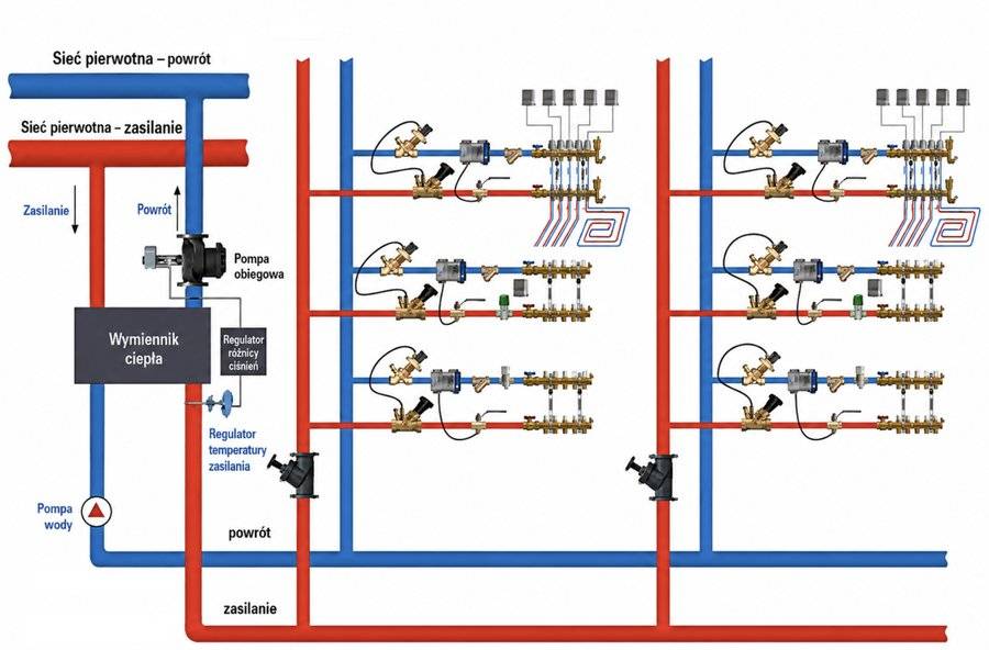
In an unbalanced system, water chooses the easiest path. Circuits with low resistance receive excess flow, while circuits with high resistance receive too little flow. Thermostats partly mask the problem, but they do not solve it: closing some valves changes the operating conditions of the others. That is why systems with variable flow increasingly use differential pressure controllers or PICV valves (Pressure Independent Control Valve), meaning pressure-independent control valves.
The simplest division looks like this:
| Type of balancing | How it works | Typical components |
|---|---|---|
Static | A fixed setting limits flow under assumed design conditions. | Presettings, riser valves, orifices, balancing valves. |
Dynamic | The component automatically stabilizes flow or differential pressure despite changes in the installation. | Differential pressure controllers, PICV valves (Pressure Independent Control Valve), dynamic flow limiters. |
Input Data for Calculations
Valve settings cannot be selected without design flows. The first mistake in many commissioning jobs is trying to regulate without information about radiator outputs, loop lengths and pipe resistance. For the designer, these data come from calculations. For an installer working on a modernization, they must be reconstructed as accurately as possible.
| Data | Where to get it | What it is used for |
|---|---|---|
Emitter output | Heat loss calculations, radiator selection, underfloor heating design. | To determine the design flow. |
Supply/return parameters | Heat source assumptions and installation design. | To determine the temperature difference . |
Pipe lengths and diameters | Plans, developed drawings, site survey. | To calculate linear losses. |
Valves, fittings and emitters | Datasheets for valves, radiators and manifolds. | To calculate local resistance and the setting range. |
Available pressure | Pump selection, district heating substation, controller setting. | To assess how much pressure must be throttled on the circuits. |
If you do not know the room outputs, start with a heat loss balance. The method is described in the article Building heat loss — calculations according to PN-EN 12831. If you already know the room output but do not have a selected emitter, the guide How to choose a radiator will help.
Calculating Flow Through an Emitter
The basis of balancing is the flow resulting from output and the assumed temperature difference between supply and return. For water in the typical temperature range of central heating systems, this practical formula can be used:
where:
- — volume flow rate [m³/h],
- — emitter output [kW],
- — supply and return temperature difference [K].
Technical valve documentation may also use mass flow rate:
where is the specific heat capacity of the medium [kJ/(kgK)]. For clean water, about can be assumed. With glycol, flows and resistance must be calculated with concentration and viscosity taken into account; more on this in the article Heating fluids — water, glycol and dilution tables.
| Emitter | Output | Parameters | Flow |
|---|---|---|---|
Radiator | 1,5 kW | 75/65°C | 0,13 m³/h |
Low-temperature radiator | 1,5 kW | 55/45°C | 0,13 m³/h |
Underfloor loop | 1,5 kW | 35/30°C | 0,26 m³/h |
Air heater / larger emitter | 5,0 kW | 55/45°C | 0,43 m³/h |
The first two examples have the same flow because in both cases the temperature difference is 10 K. Flow is determined by output and , not by the label "standard radiator" or "low-temperature radiator" itself. The conclusion is simple: the smaller the temperature difference, the higher the flow for the same output. That is why replacing a boiler with a heat pump or lowering operating parameters without checking the hydraulics often reveals pipe diameters that are too small, resistance that is too high or poorly selected valves.
Circuit Resistance and the Critical Circuit
Each circuit has its own hydraulic resistance. It consists of supply and return pipes, fittings, tees, valves, the radiator or manifold and the control valves. A simplified notation looks like this:
The critical circuit is the one that requires the greatest differential pressure at design flow. Most often it is the farthest circuit, but not always. A short branch with a small diameter and many fittings may have higher resistance than a longer section made with a larger diameter.
In practical balancing, the critical circuit is treated as the reference point. The pump or controller must provide the pressure it requires. Nearer circuits usually have lower resistance, so the excess pressure must be throttled at the valve presetting or balancing valve. This is exactly why the nearest radiator, which "heats the best", should often have the smallest setting.
To calculate flow, velocity and pressure drops in pipes, use the central heating pipe diameter selection calculator. A broader discussion of resistance can be found in the article Calculating pressure drops and selecting diameters in a heating system.
Valve Settings and Balancing Components
Balancing can be performed at different levels of the installation. In a single-family house, thermostatic valve presettings and manifold adjustment are often enough. In an apartment building, riser valves, differential pressure controllers or dynamic valves are already needed. In office and HVAC systems, PICVs are common because emitters operate with variable flow.
| Component | What it controls | When to use it | Typical mistake |
|---|---|---|---|
Thermostatic valve presetting | Flow through a single radiator. | Small and medium radiator systems. | All valves set to maximum. |
Riser valve | Flow through a riser or branch. | Multi-riser systems and modernizations. | No correction after pump or heat source replacement. |
Balancing valve with test points | Flow and pressure drop measurement. | Commissioning with a protocol and flow control. | Selection outside the useful measuring range. |
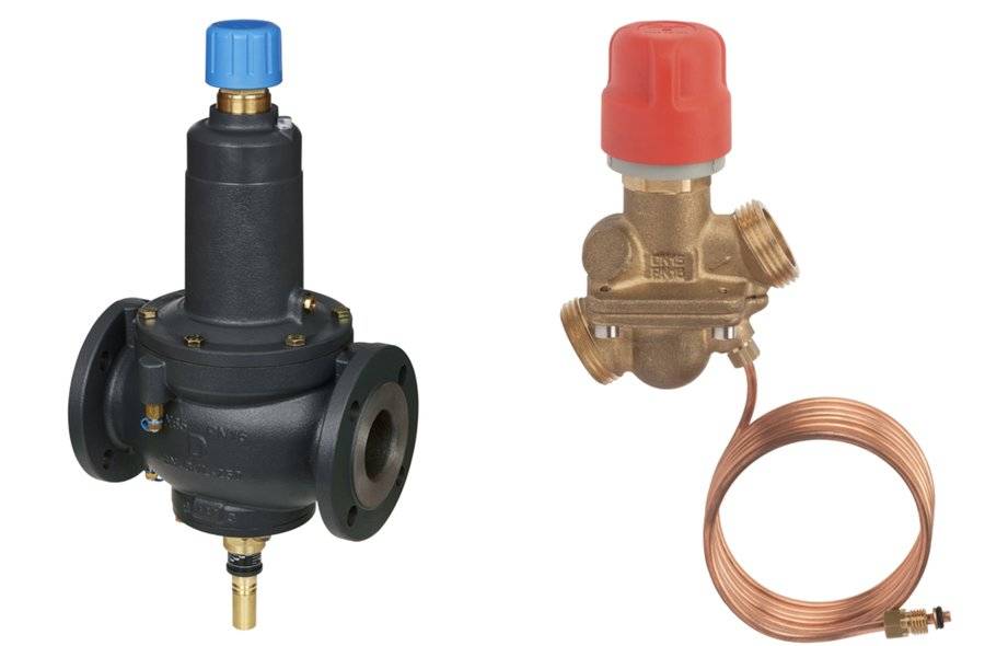
Differential pressure controller | A stable differential pressure for a branch or riser. | Variable-flow systems. | Installation without checking the required setting range. |
Selecting a Balancing Valve and Kvs
Valve selection comes down to linking flow with the required pressure drop. In this article, we focus on how the pressure drop across the valve affects the rest of the circuits; detailed theory of the Kvs coefficient and valve authority can be found in the separate guide Control valve authority — Kvs coefficient.
The basic formula is:
where:
- — valve flow coefficient [m³/h],
- — flow through the valve [m³/h],
- — pressure drop across the valve [bar].
If the valve is too large, at the required flow it works close to the closed position. Control is then nervous, and a small movement of the stem causes a large change in flow. If the valve is too small, it will only provide the flow at a large pressure drop, which increases resistance, noise and pump requirements.
In practice, the designer should check not only , but also valve authority. Good control properties are obtained when the valve has a noticeable share in the total resistance of the controlled part of the installation. Too low an authority means that flow is determined mainly by the rest of the circuit, not by the valve. Too high an authority, on the other hand, is sometimes paid for with an unnecessarily large pressure drop.
For a quick check of these relationships, use the Kvs and valve authority calculator.
PICV and Differential Pressure Controllers
PICV stands for Pressure Independent Control Valve. In Polish practice, it is described as a pressure-independent control valve or a pressure-independent control and balancing valve. Such a valve combines flow control with automatic limiting of the influence of differential pressure changes in the installation.
In variable-flow systems, static balancing alone is not always enough. When thermostatic valves close some radiators, the differential pressure available to the remaining circuits rises. This can cause noise, excess flow and worse control. That is why dynamic components are used in larger systems.
| Solution | Advantage | Limitation | When to choose it |
|---|---|---|---|
Static valves | Simple and inexpensive. | Sensitive to flow changes in other circuits. | Small systems, constant or slightly variable flow. |
controller | Stabilizes the operating conditions of a riser or branch. | Requires the correct setting range and installation location. | Apartment buildings, modernizations, systems with thermostats. |
PICV (Pressure Independent Control Valve) | Combines flow limitation and pressure-independent control. | Requires a minimum differential pressure to operate; the value depends on the manufacturer. | HVAC emitters, offices, variable-flow systems. |
No single universal minimum pressure drop value should be given for PICVs. Catalogues list different requirements, often in the range of a dozen or several dozen kPa, but the specific valve type and flow range ultimately decide. This value, often defined as or starting pressure, must be provided by the pump so that the valve control mechanism starts working correctly. The design must therefore check whether the pump or controller will provide the minimum at the most unfavorable emitter.
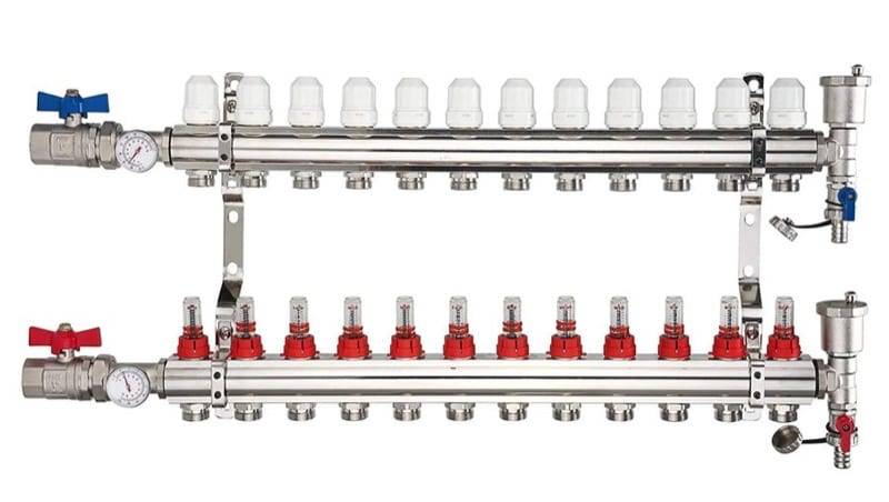
Balancing Underfloor Heating
Underfloor heating is balanced similarly to radiators: first, the loop output and design flow must be known. The difference is its greater thermal inertia. Adjusting the rotameter setting does not give a reliable response after a few minutes, because the floor reacts with a delay.
A typical mistake is treating the rotameter as a tool for fixing a bad design. If the loop is too long, the pipe diameter is too small and the loop resistance is much higher than the others, simply increasing the setting will not provide the flow. The pump may operate at a higher speed, but then the shorter loops will receive excess flow.
Newer manifolds may include automatic flow limiters or dynamic solutions. They make commissioning easier and limit the influence of pressure changes, but they also require correct selection of loop lengths, flow and operating range. Details of loop calculations are described in the article How to calculate underfloor heating step by step, and lengths and spacing can be checked in the underfloor heating calculator.
Calculation Example
Consider a small radiator system with three emitters. All operate at 55/45°C parameters, so .
| Emitter | Output | Design flow | Circuit resistance without throttling |
|---|---|---|---|
Radiator A — near circuit | 1,2 kW | 0,10 m³/h | 8 kPa |
Radiator B — middle circuit | 1,8 kW | 0,15 m³/h | 14 kPa |
Radiator C — farthest circuit | 2,4 kW | 0,21 m³/h | 22 kPa |
Radiator C is the critical circuit because it requires 22 kPa at design flow. If the pump is to provide 22 kPa for the farthest emitter, excess pressure appears on the nearer circuits:
- circuit A: to be throttled,
- circuit B: to be throttled,
- circuit C: as little additional resistance as possible.
Now valve settings or balancing valves can be selected so that, at the required flow, they generate the appropriate pressure drop. For radiator A, the valve should restrict the flow more strongly than for radiator B. This explains why the nearest radiators should not be "fully open" just because they are close to the source.
In a real design, these calculations are supplemented by checking the setting range of the specific valve from the datasheet. It must not be assumed that every head and every thermostatic valve can achieve any flow at any pressure drop.
Commissioning Procedure and Balancing Protocol
Hydraulic balancing should end with a protocol. Without it, there is no way to know whether the installation was commissioned according to the design or which settings to return to after modernization. When accepting and handing over water-based heating systems, it is worth considering the requirements of current editions of standards from the EN 14336 group concerning the installation and commissioning of water-based heating systems.
The basic procedure is as follows:
- Check that valves and fittings comply with the design and selection sheets.
- Flush, fill and vent the installation.
- Set the pump or differential pressure controller to the mode specified in the design.
- Enter valve presettings.
- Measure flows or pressure drops at measuring valves.
- Correct settings using the proportional method or electronic measuring instruments.
- Record the result in the protocol.
The proportional method consists of correcting circuits in relation to a reference circuit so that flow deviations decrease across the entire branch. The computer method uses a measuring instrument and valve data stored in the measuring device. Regulation "by return temperature" can be useful diagnostically, but it is an approximate method. Return temperature depends not only on flow, but also on the current output of the emitter, room temperature, inertia and thermostat operation.
| Measuring point | Design flow | Setting | Measured flow | Notes |
|---|---|---|---|---|
Riser P1 | 0,42 m³/h | 2,5 | 0,41 m³/h | Within tolerance. |
Riser P2 | 0,58 m³/h | 3,0 | 0,56 m³/h | After pump setting correction. |
Most Common Mistakes
The biggest mistake is the lack of design flows. If the design does not include flows for radiators, loops and branches, the contractor is left with an installation that cannot be set correctly without additional calculations. The second common mistake is leaving all settings in the maximum position. Such an installation may heat, but it usually operates with excess flows and too high a pump speed.
Typical problems also include:
- selecting a pump "with a safety margin" without differential pressure control,
- trying to regulate an airlocked or contaminated installation,
- oversizing valves relative to the real flow,
- no controllers in variable-flow systems,
- treating return temperature as an unambiguous flow measurement,
- no update of settings after thermal modernization, heat source replacement or a change in operating parameters.
Lack of balancing can often be recognized even without a measuring instrument. Warning signs include: noise at thermostatic valves, cold radiators at the ends of the installation, very hot returns on near circuits, large temperature differences between rooms, the need to run the pump at high speed and cycling or poorer operation of the heat source.
FAQ
Is Hydraulic Balancing Needed in a Single-Family House?
Yes, although it is usually simpler than in an apartment building. In a small house, correct underfloor loop flows, radiator valve presettings and a sensible pump setting are often enough. If the installation has several floors, long circuits or a mixed radiator + underfloor heating layout, the lack of balancing quickly becomes visible.
What Is the Difference Between Throttling and Hydraulic Balancing?
Throttling is a colloquial term for restricting flow, usually on a valve or orifice. Hydraulic balancing is a broader process: it includes calculating flows and resistance, selecting valves and fittings, setting values, measuring and preparing the commissioning protocol.
Are Thermostatic Valves Enough?
Thermostatic heads alone do not replace balancing. The head reacts to room temperature, but it does not guarantee design flow. A valve presetting or another component limiting the flow to the calculated value is needed.
When Should PICV Be Used?
PICV is worth considering where flow changes often: in office systems, at HVAC emitters, fan coils, air heaters and extensive systems with automation. In a small, simple radiator system, less expensive static solutions are usually enough.
Does the Installation Need to Be Set Again After Pump Replacement?
Yes, if the new pump has a different characteristic, control mode or higher available differential pressure. Replacing a pump without checking the settings can turn a quiet installation into one with noise and excess flows.
Summary
Hydraulic balancing starts with numbers: emitter outputs, flows and circuit resistance. Only then does it make sense to talk about valve settings. The farthest or highest-resistance circuit determines the required pressure, and nearer circuits must be throttled so that they do not take flow away from the rest of the installation.
In constant-flow systems, static balancing is often enough. In variable-flow systems, differential pressure control or dynamic valves are needed. Without this, thermostatic valves, the pump and the heat source operate under changing conditions, and control becomes random.
To calculate pipe flows and resistance, use the heating pipe diameter selection calculator. To check valve selection, Kvs and authority, use the valve authority calculator.
Back to articles list