
Building Heat Loss Calculations per EN 12831 — step-by-step guide
14 kwietnia 2026 | Heating
A heat loss balance is the foundation of every heating system design. The correct result determines boiler and heat pump sizing, radiator dimensions, underfloor heating loop length and pipe diameters. Roughly 80% of under-heating issues in completed installations come not from faulty workmanship but from flawed design calculations at the very start. This guide walks you step by step through the PN-EN 12831-1:2017 methodology — the current Polish implementation of the European standard for design heat load calculations.
If you need a quick check of a wall's thermal transmittance, use our U-value calculator. This article supports all calculators in the heating category.
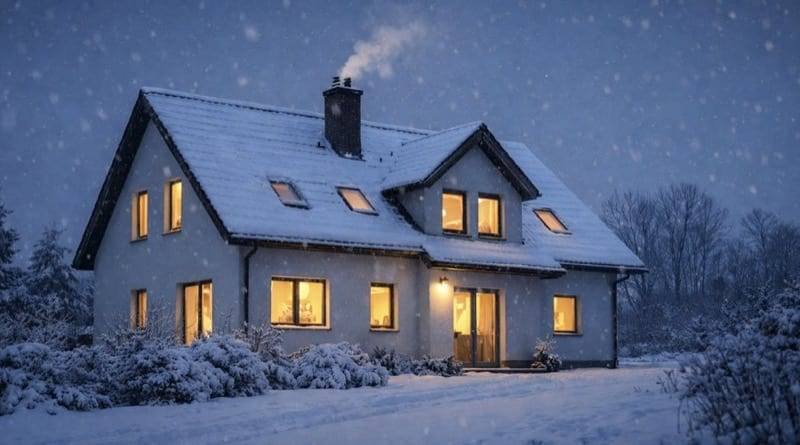
What "heat loss" actually means — and why it is not your gas bill
A critical distinction that resolves 90% of misunderstandings between designer and client:
- Design heat load () — the power expressed in watts [W] that the heat source must deliver on the coldest design day to maintain the required indoor temperatures. This figure is used for sizing the boiler, heat pump, radiator or underfloor loop. It is calculated per EN 12831.
- Annual useful energy demand () — the energy in kilowatt-hours per year [kWh/year] actually consumed over the heating season. This figure determines heating bills. It is calculated using a different methodology (EN ISO 52016 and the national regulation on the methodology for calculating the energy performance of buildings).
Confusing the two is the most common mistake among clients — and, unfortunately, some designers too. A 20 kW boiler does not "consume 20,000 kWh per year." The annual demand for a 150 m² house built to WT 2021 is around 9,000–12,000 kWh, even if the design load is 6–7 kW. EN 12831 answers only the first question: what power heat source do you need.
The full picture is complemented by the article on the new Polish Technical Conditions 2026, which affect the energy performance indicator EP and indirectly — annual demand results.
Components of the design heat load
Per PN-EN 12831-1:2017, the total design heat load for room is:
where:
— transmission losses through building envelope elements (walls, windows, roof, floor) [W]
— ventilation losses (air exchange with the environment) [W]
— reheat power after a setback (optional) [W]
The total for the whole building is the sum of across all heated rooms. Important: you cannot calculate the building "as a whole" — the standard requires room-by-room calculations, because radiator sizing depends on them.
Transmission losses
Transmission losses are the heat flux escaping through envelope elements driven by the indoor-outdoor temperature difference:
where is the transmission heat loss coefficient [W/K] for four envelope categories:
— elements directly to outdoor air (external wall, window, roof)
— elements to an unheated space (unoccupied attic, garage)
— elements in contact with ground (ground floor slab, basement wall)
— elements to another temperature zone inside the building
How to calculate H_T for a single element
For each building element:
where:
— area of the element [m²]
— thermal transmittance [W/(m²·K)]
— dimensionless temperature reduction factor
The factor (also denoted in some editions — nomenclature varies) accounts for the fact that not every element borders the outdoor temperature . For an external wall . For an element between a heated space and an unheated attic . For ground floor slabs the detailed methodology of EN ISO 13370 is used, accounting for characteristic dimension and edge insulation thickness.
A detailed discussion of the U-value itself — layer-by-layer calculation, and treatment, WT requirements — is in the article Thermal transmittance U — a guide. For fast U-value calculation of a multi-layer element use the U-value calculator. Thermal conductivity values for insulation materials are in the article Lambda of building materials.
Thermal bridges — do not skip them
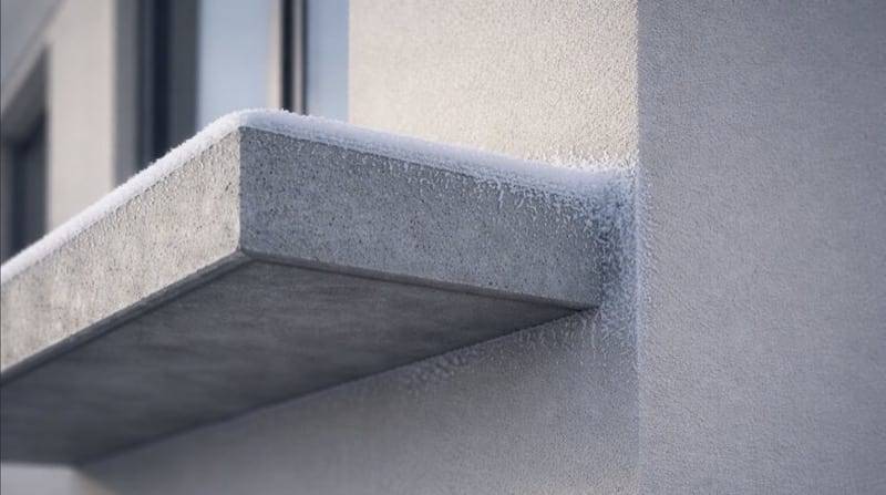
Thermal bridges are local reductions of insulation quality in a wall — typically caused by insulation interruptions (balcony, lintel, plinth) or geometry changes (corners). Ignoring them underestimates the balance by 10–20%, which translates to under-heating in real operation.
PN-EN 12831-1:2017 favours a linear calculation — for each bridge:
where is the linear thermal transmittance of the bridge [W/(m·K)] and its length [m].
Typical values:
| Type of thermal bridge | ψ [W/(m·K)] |
|---|---|
| External wall corner | 0.05–0.10 |
| Window / door lintel | 0.05–0.15 |
| Plinth (wall-to-foundation junction) | 0.30–0.50 |
| Cantilevered concrete balcony | 0.50–0.85 |
| Intermediate floor slab | 0.05–0.10 |
| Roof eaves | 0.05–0.15 |
As a simplification — when detailed values are unknown — engineers commonly add 10–15% to the of each element (the so-called ). The exact value depends on envelope geometry, detailing, and the project's approach — it is a practical simplification used for preliminary calculations, not a universal standard allowance. In detailed design the bridges should be calculated linearly ().
Ventilation losses
The second loss stream is air exchange with the environment:
where:
— volumetric airflow exchanged with outside [m³/h]
— air density times specific heat divided by 3600, in [Wh/(m³·K)]; derived from J/(m³·K)
How to determine
The airflow per room is taken as the maximum of three components:
- Hygienic requirement — from the ventilation balance (air changes per hour or airflow per person). For dwellings: PN-83/B-03430 defines minimum exhaust flows (kitchen 70 m³/h, bathroom 50 m³/h, WC 30 m³/h).
- Infiltration — air ingress through envelope leaks. In the simplified method (from EN 12831:2006, still commonly used), it is derived from (air changes at 50 Pa, from a Blower Door test) and shielding coefficients , : . The full PN-EN 12831-1:2017 method is more elaborate — based on envelope permeability , pressure balance and room height; most engineering practice still uses the simplified version.
- Supply/exhaust balance — with mechanical ventilation the balance point difference must be covered.
Heat recovery in the formula
With a recovery efficiency (typically 0.70–0.90), the "effective" airflow passing through the unit is reduced:
Infiltration is added separately — because air entering through leaks does not pass through the recovery unit. Details of ventilation sizing are in the articles Mechanical vs natural ventilation and Air flow calculation.
Reheat power after setback
If the installation uses programmed temperature setbacks (e.g. at night), after the setback the heat source must "bring up" the rooms within a finite time. Additional power:
where is the floor area [m²] and [W/m²] depends on reheat time, temperature drop and building thermal mass. For a typical 3 K nightly setback and 2 h reheat, is around 10–20 W/m².
In practice, in buildings with underfloor heating (high thermal mass) is usually omitted — a setback is barely effective anyway with floor heating. In radiator-based systems, especially in lightweight buildings, reheat is worth including.
Design temperatures
External design temperature — Polish climate zones
The zoning and design external temperatures are set by PN-82/B-02402 and the Polish national annex to EN 12831. Poland is divided into five climate zones:
| Zone | θ_e [°C] | Area (examples) |
|---|---|---|
| I | −16 | Baltic coast, West Pomerania (Szczecin, Koszalin) |
| II | −18 | Greater Poland, Lower Silesia, Kujawy (Poznań, Wrocław, Bydgoszcz) |
| III | −20 | Central and eastern Poland (Warsaw, Łódź, Lublin) |
| IV | −22 | Suwałki region, north-eastern Poland |
| V | −24 | Mountains above 800 m a.s.l. (Zakopane, Bieszczady) |
Indoor temperature — by room type
Minimum design indoor temperatures follow the Polish Technical Conditions (Regulation of the Minister of Infrastructure, §134 appendix) and the national annex to EN 12831:
| Room type | θ_int [°C] |
|---|---|
| Living room, bedroom, office | 20 |
| Kitchen (with openable window) | 20 |
| Bathroom, WC with washbasin and shower | 24 |
| Utility rooms, heated garage | 16 |
| Staircase, corridor, hall | 16 |
| Gyms, workshops | 18 |
Worked example — 150 m² single-family house
Let's calculate a single-storey house with a usable attic, 150 m² of heated floor area, located in Poznań (zone II, °C). Parameters:
- External wall area: 180 m², W/(m²·K)
- Window area: 28 m², W/(m²·K)
- Roof area: 95 m², W/(m²·K)
- Ground floor slab area: 75 m², W/(m²·K),
- Heated volume: m³
- Mechanical ventilation with recovery, , rate h⁻¹
- Airtightness: h⁻¹ (recommended by WT for buildings with mechanical ventilation — a guideline, not a hard limit, per §2.3.3 of the regulation appendix), ,
- Average indoor temperature: °C (difference K)
- Linear thermal bridges addition: around 10%
Step 1: Transmission losses (without bridges)
| Element | A [m²] | U [W/(m²·K)] | b | H_T [W/K] |
|---|---|---|---|---|
| External walls | 180 | 0.20 | 1.00 | 36.0 |
| Windows | 28 | 0.90 | 1.00 | 25.2 |
| Roof | 95 | 0.15 | 1.00 | 14.3 |
| Ground floor slab | 75 | 0.25 | 0.60 | 11.3 |
| Total H_T | — | — | — | 86.8 |
With a 10% thermal bridge allowance: W/K.
W.
Step 2: Ventilation losses
Mechanical flow: m³/h. Through the recovery unit (η = 0.80): m³/h.
Infiltration: m³/h.
Total: m³/h.
W.
Step 3: Total heat load
| Transmission losses Φ_T | 3,629 W |
|---|---|
| Ventilation losses Φ_V | 1,111 W |
| Reheat Φ_RH (underfloor heating — omitted) | 0 W |
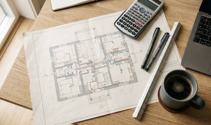
| Φ_HL — design heat load | ~4,740 W ≈ 4.8 kW |
| Specific load | ~32 W/m² |
A figure of ~32 W/m² is typical for a WT 2021 house with heat recovery. For comparison:
- Passive house (PHI certified): 10–15 W/m²
- Energy-efficient WT 2021 house with recovery: 25–40 W/m²
- WT 2008 house: 50–70 W/m²
- Old building without retrofit: 100–150 W/m²
Without heat recovery (full 210 m³/h plus infiltration), would rise to around 3,300 W and to about 6.9 kW — showing how much recovery saves on design load.
Common mistakes
- Skipping thermal bridges — underestimates the balance by 10–20%. On site this means cold corners, frost and mould.
- Confusing design load with annual consumption — "a 20 kW boiler burns 20,000 kWh" is a myth. Peak power and energy are different quantities.
- Wrong climate zone — a Warsaw designer copies a Suwałki template (−22 °C) or vice versa.
- Oversimplified ventilation — assuming an average air-change rate instead of calculating per room.
- Ignoring infiltration with heat recovery — even a tight building has bypassing the exchanger.
- Wrong ground method — using instead of per EN ISO 13370 overestimates floor losses.
- Incorrect — a designer uses 20 °C for a bathroom instead of 24 °C; the loss for that room is underestimated by 20%.
What next with the result
The design is the input to a chain of subsequent decisions:
Heat source sizing
- Gas or pellet boiler — size for + a 10–20% reserve for DHW and safety margin.
- Heat pump — more subtle. It is sized for the so-called bivalent point (usually −5 to −7 °C), not the full . For lower temperatures a resistance heater or an auxiliary source kicks in (bivalent mode). Pump capacity is typically 60–80% of . That is why "peak power" from the balance ≠ "heat pump capacity" from an offer. A dedicated heat pump article is forthcoming.
Sizing of internal systems
- Radiators — split room by room and size radiators. Helpful tools: radiator sizing calculator and the guide Radiator sizing.
- Underfloor heating — split into specific loop power and loop length. See underfloor heating calculator and the comparison Underfloor vs radiators.
- Heating pipe diameters — gives the working fluid flow, which gives the pipe diameters (heating pipe sizing calculator and the article on heating fluids).
- Expansion vessel and safety valves — sized for the water volume in the system, which follows from the pipe diameters and lengths.
Frequently asked questions (FAQ)
Can I use a W/m² indicator instead of a full balance?
Only for a very rough investment check. A 40–60 W/m² indicator for a WT 2021 house gives an approximate peak power, but does not replace the room-by-room balance required by the standard for radiator and loop sizing. For a quick quotation — yes. For detailed design — no.
How to estimate losses of an existing building without documentation?
An inventory is required: surface measurements, estimates based on insulation thickness and type (or thermography), conservative values for bridges. A Blower Door test provides a reliable . Without insulation data, typical values by construction era (WT 1997, WT 2002, WT 2008) are assumed.
Has PN-EN 12831 superseded PN-B-03406?
Yes. PN-EN 12831-1:2017 (adopted in Poland in 2017) replaced the older PN-B-03406:1994. Key differences: more detailed handling of thermal bridges, reference to EN ISO 13370 for ground, different terminology (factor vs , explicit separation of infiltration and mechanical ventilation).
How to include solar gains in the design balance?
You do not. is the power required in the worst conditions — a sunless, overcast, freezing day. Solar and internal gains are accounted for only in the annual energy demand calculation (EN ISO 52016, the national energy certification methodology). Mixing the two methodologies is a common beginner mistake.
Does WT 2026 change how losses are calculated?
No. The official reference for maximum values (wall ≤ 0.20 W/(m²·K), roof ≤ 0.15, window ≤ 0.9) remains WT 2021 (Journal of Laws 2020 item 2351, in force 31 December 2020). According to current drafts, WT 2026 mainly adjusts the energy performance indicator EP and renewables requirements, not the U-values — but the final shape depends on publication in the Journal of Laws. For the heat loss balance, the formula and methodology remain unchanged in any case; only the annual energy demand changes, computed by a different methodology. Details in the new Technical Conditions 2026 article.
What about heat losses in passive houses?
Passive house per PHI: W/m² ("heizlast"). Five to seven times lower than standard houses. Achieved by a combination: envelope around 0.10–0.12 W/(m²·K), recovery with , airtightness h⁻¹, windows with . Result — a 150 m² house with a 1.5 kW demand, often heated solely by the ventilation post-heater.
Can I calculate heat losses in Excel?
Technically yes — the formula is simple. The problem is the point of the exercise: EN 12831 requires calculations room by room, not a single-shot building total. For a 15-room house with individual , bridges and ventilation flows, that is hundreds of cells and a source of errors. That is why designers use dedicated software (OZC, Purmo, Audytor) — or online calculators like those at kalkulatorpro.pl, which automate the balance components.
An accurate heat loss balance is the most important step in heating system design. An error here propagates across the whole investment — from an oversized boiler through unbalanced underfloor loops to excessive energy consumption. PN-EN 12831-1:2017 provides a rigorous framework that, with some attention, yields precise and comparable results between designers. The rest is calculators, tables and experience — all three are available at kalkulatorpro.pl.
Back to articles list